ID |
Date |
Author |
Category |
Subject |
|
43
|
Fri Feb 28 00:18:16 2025 |
Tamina | General | Kalibration UV Monitor im Laserlabor |
Der UV Monitor steht in der Reflexion des PBSC auf dem Lasertisch im Laserlabor.

P_Transmission = (1-(0.9364 * cos^2(0.0349* (theta - 33.014)) + 0.06043)) *P_Reflex

theta ist der Winkel der lambda/2 Platte
Es muss jedoch noch eine min. 3 % zusätzliche Unsicherheit durch manuelle Einstellung ddes Winkels ect. angenommen werden (für die reine cos^2 Funktion; ohne R_reflex und 1-)

Anmerkung: Aufpassen bei bestimmen der Werte: der cos^2 Fit wurde im Rad Modus gemacht! |
|
42
|
Thu Feb 27 23:01:26 2025 |
Danyal, Konstantin, Sebastian | Calibration | Delaytime measurement |
Yesterday, we forgot to take the transit time of the PMT's into account when we set up the delay times of the detectors PMT middle, PMT north, PD SW, and PD NW.
Today we did the measurement again and took transit times into account. Additionally, we finalized the cabling for the XUV detector.
|
Detector | Delay
| |
PMT middle | 1211(1) ns | |
PMT north | 1211(1) ns | |
PD SW | 1257(1) ns | |
PD NW | 1257(1) ns | |
XUV detector | 1257(1) ns
|
|
|
41
|
Thu Feb 27 21:23:02 2025 |
Jens | DAQ | Python Data Channels |
Python variables and names in DAQ
Because the Name of variables in DAQ doesnt match the the real variables, here is List of the channels and what value is in this channel

UTC : Time in seconds (UTC time in seconds)
TIMERMS : Time in 100ms (UTC time, only digits after decimalpoint)
VOLTECOOL : E-Cooler scaled Voltage / Volt (value / -1.e+4)
COBRASETWL : Laser Frequency / MHz (Thz Output of WLM / 1e08)
ATOSWL : Gentec1 "COM5" Southwest / pW (W of Gentec / 1e12)
ATOSINTENSITY : Gentec2 "COM6" Northwest / pW (W of Gentec / 1e12)
ATOSNUMIFM : not used (not used, only 1 digit)
STATFLUKE : not used (not used, only 1 digit)
STATATOS : not used (not used, only 1 digit)
COBMOTHI : E-Cooler raw Voltage / V (value / -1.e+8)
COBMOTLO : not used
COBNUMLOOP : not used
COBSTAT : not used
ATOSCNTR : not used
COBFROMWL : not used
COBTOWL : not used
COBINCREM : not used
COBSTEPNR : not used
HEINZREGVOLT : not used
STATAGILENT : not used |
|
40
|
Thu Feb 27 20:21:31 2025 |
Sebastian | General | 10 MHz Ref Clock (Butis) |
10 MHz Referenz Clock von BUTIS mit AFG als externl clock verbunden.
Wird benötigt das die Bunch Kavität (DDS System) in Phase mit AFG (Laserreprate) ist. |
|
39
|
Thu Feb 27 16:30:57 2025 |
Konstantin und Rodolfo | DAQ | HF Signal |
| We have exchanged the HF-Signal in the DAQ Electronic: from Dummy-HF to the real HF from accelerator. |
|
38
|
Thu Feb 27 11:19:55 2025 |
Danyal | Accelerator | pictures of the ion beam from 26.02.2025 |
Hier sind noch ein paar Bilder vom Ionenstrahl , wie er gestern Abend war. |
| Attachment 1: Schottky_pick-up_Bild.jpg
|
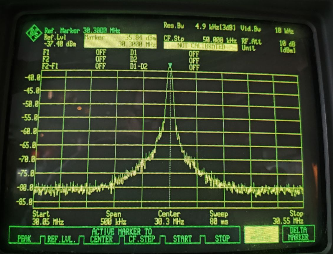
|
| Attachment 2: Schottky_resonator_Bild.jpg
|
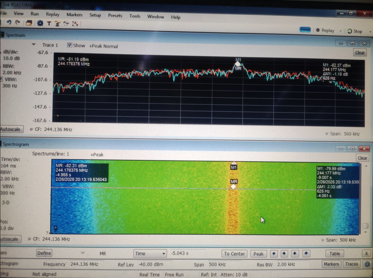
|
| Attachment 3: gebunchter_Strahl_im_ESR.jpg
|
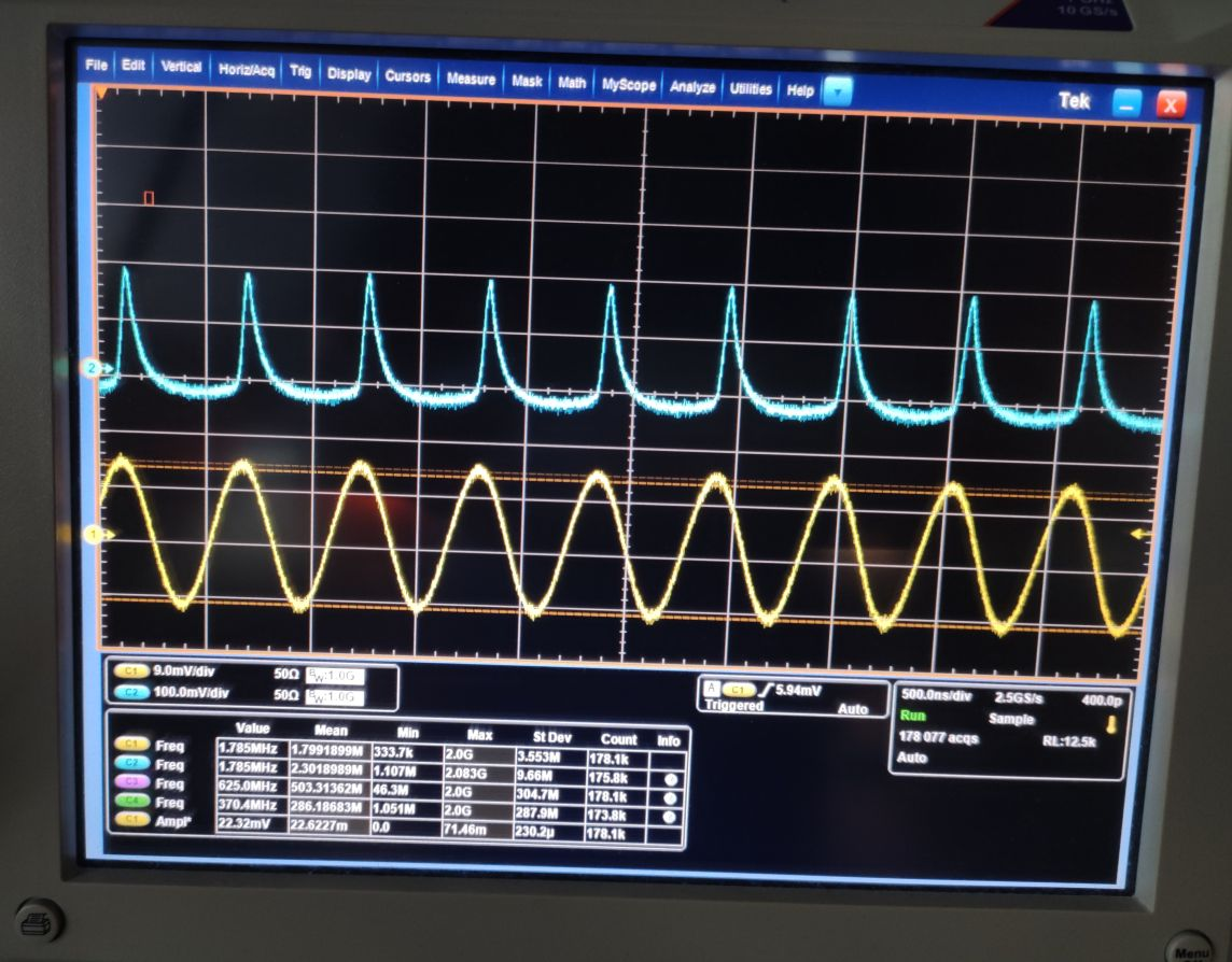
|
|
37
|
Thu Feb 27 10:52:32 2025 |
Rodolfo | Detectors | Taking PMTs into operation |
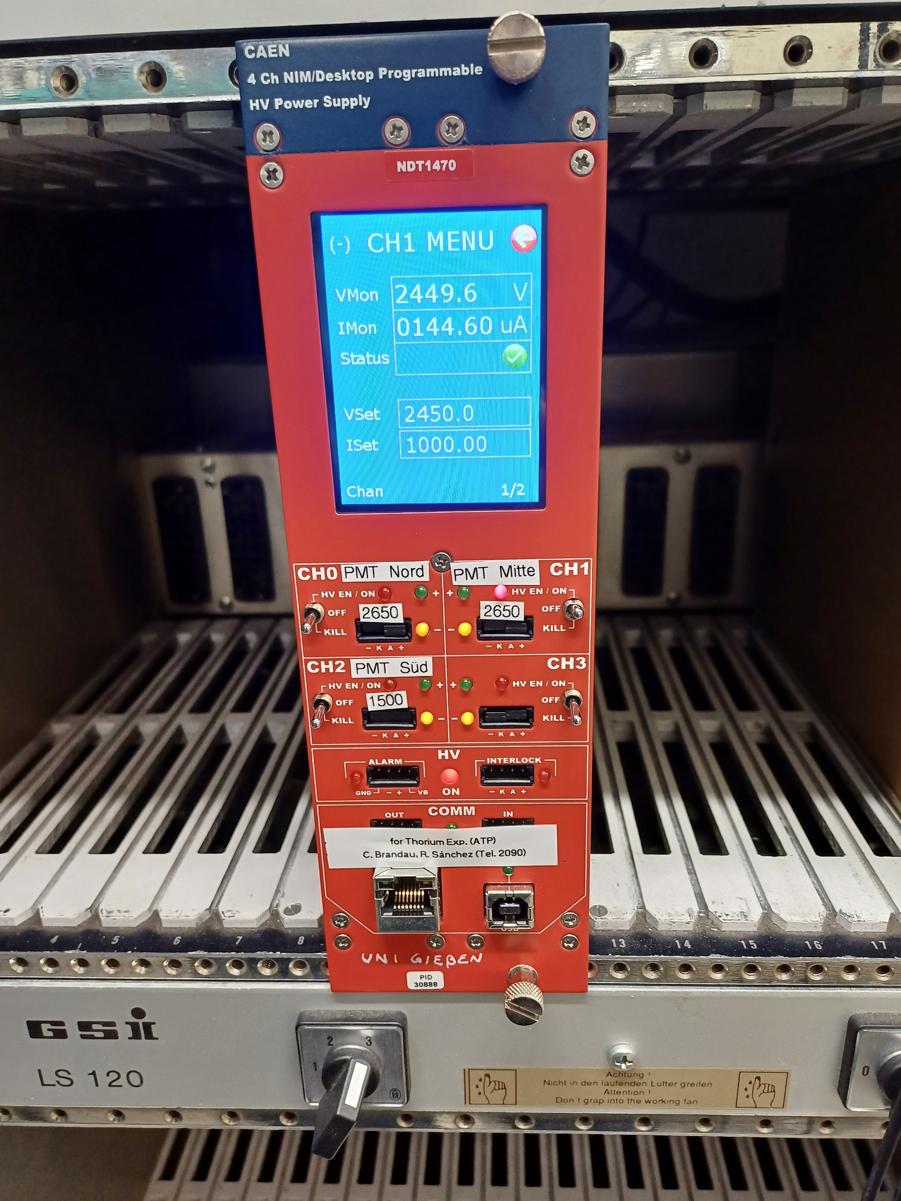
PMT Nord the power supply (CH0) is giving an alarm already by an applied voltage of -1707 V (operation voltage is -2450 V). It is leaking to much current, larger than the set value of 310 uA. See attached picture 20250227_105411.jpg .
- 10:50 I am trying to identify the issue.
- 14:00 I increased the current limit Iset to 500 uA and the PMT was working OK by an applied voltage of -2500 V. After few minutes the HV power supply showed again an alarm. Afterwards the HV power supply CH0 is not giving any voltage anymore :-/
- 14:15 We Danyal and me, tried to get the PMT working using an alternative power supply. By a voltage of -2500 V the PMT does not show any signal.
- 16:50 I tested the HV power supply (CH0). It is working again.
Once the cave is opened, we will check this PMT in situ
PMT Mitte It is working fine by an applied voltage of -2450 V (current of 144.6 uA). See attached picture 20250227_143518.jpg. Its dark count rate is < 10 Hz by a threshold of -26 mV measured in the oscilloscope. |
| Attachment 1: 20250227_105411.jpg
|
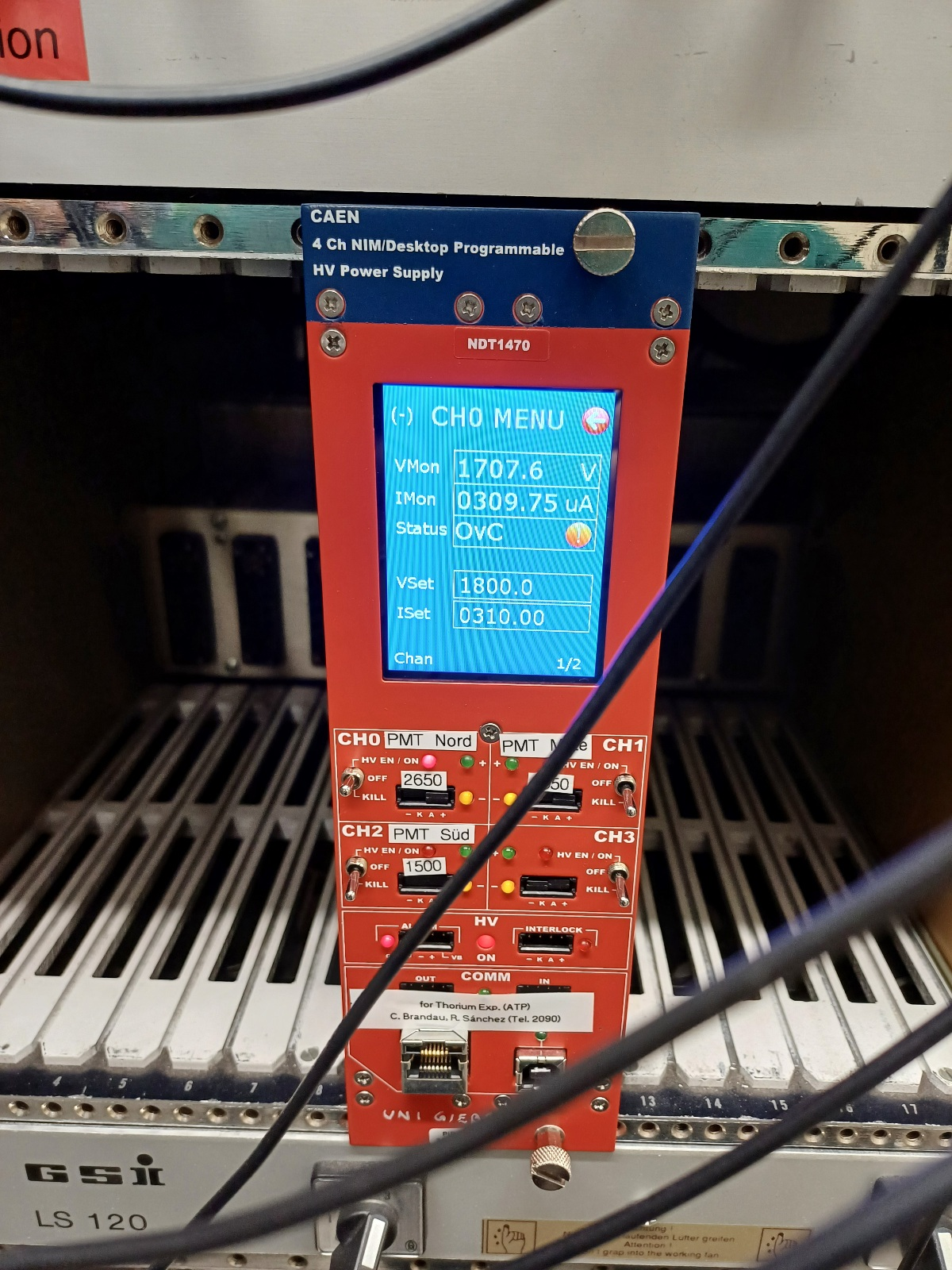
|
| Attachment 2: 20250227_143518.jpg
|
|
|
36
|
Thu Feb 27 09:59:08 2025 |
Konstantin | Calibration | HV-Divider |
The readout of the HV divider runs on a RaspberryPi inside the HV-cave of the electron cooler.
Starting from 2025-02-27 09:42, the divider ratio was changed from 248517 to 248515. Usually, the
readout should run continuously. If not, the following procedure must be applied:

1. Connect to the Rasperry:
  ssh esr_cooler@140.181.95.195 (ask Konstantin for pwd)
2. Display logging screen:
  screen -R signals (Typically you can use arrow up)
3. Stop logging, if it is running:
  Option 1: Type "stop" and press enter.
  Option 2: control + C
4. Restart logging:
  "python main.py -i 0.1 -f loss_current -d 3 5"
5. Detach screen:
  control + a + d
6. Disconnect from Raspberry |
|
35
|
Thu Feb 27 09:38:04 2025 |
Konstantin & Danyal | Detectors | Laufzeit Messungen |
Gestern Abend haben wir die Signal Laufzeiten im gemessen:

PMT Mitte: 1213 ns (bis zur Messhütte ohne DAQ sind es 1025 ns)
PMT Nord: 1212 ns
PD Nord: 1171 ns (ohne DAQ sind es 1172 ns)

Weil PD Nord zu kurz war und wir es mit einem Gate&Delay nur um >40 ns Sekunden verschieben konnten, was gerade nicht reichte,
wurde entschieden dann PD Nord ein kleines delay zu geben, damit es 1240 ns sind.
(Es gab kein passendes Kabel um anzupassen)

Danach haben wir alle andere Laufzeiten mit Gate&Delay daran angepasst.
PD Nord: 1240 ns
PD Süd: 1240 ns
PMT Nord: 1240 ns (offset war 27 ns, extra delay ist 165,88 ns)
PMT Mitte: 1240 ns (offset war 28 ns, extra delay ist 166,2 ns)
XUV Anode: 1008 +/- 1 ns (nur bis zu CFD in Messhütte) Delay muss noch angepasst werden! |
|
34
|
Wed Feb 26 18:53:52 2025 |
Danyal | Accelerator | ESR settings |
Date: 26.02.2025 @  18:35

E-cooler:  HV = 157366 +/- 1 V  (HV divider value)
E-cooler current = 200 mA (scale:  1V --> 10 mA)

Schottky f_rev = 1.782012 +/- 1 MHz (measured value)
f_b = 1.782013 MHz (set value)

orbit length in ESR = 108.5 m (based on experience, injection is further out, not central)

y = 1.30796
ß = 0.64456


We have 1 ion bunch in the ESR |
|
33
|
Tue Feb 25 14:51:52 2025 |
Danyal | General | Experiment Acceptance |
Today, 25 FEB 2025 at 9:00 AM, our experiment was reviewed carefully by the safety committee.
The experiment was accepted without problems.
All was fine, only minor comments were made and only a few short-notice actions were required.

The procedure has become much more complicated and lengthy over time, though.
(Something to keep in mind.)

Many thanks to the whole team !! |
|
32
|
Tue Feb 25 13:12:01 2025 |
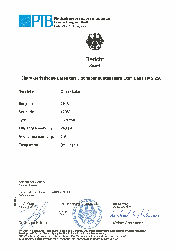
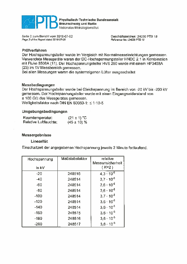
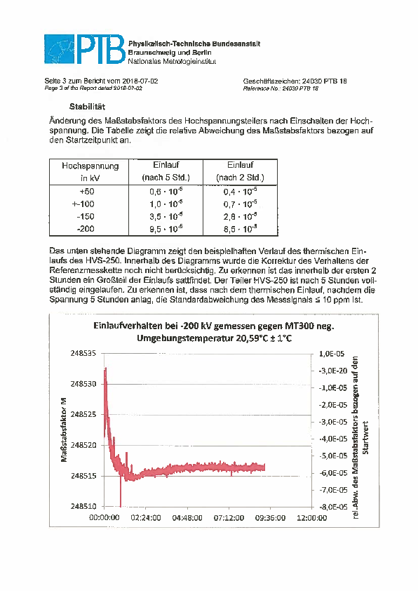
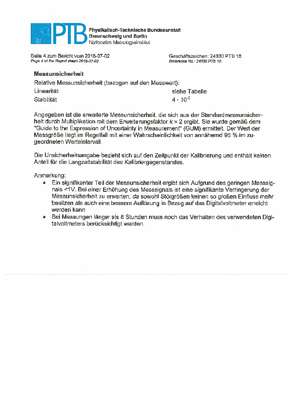
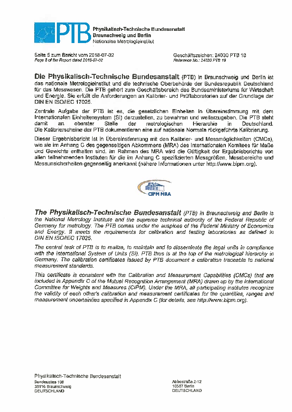
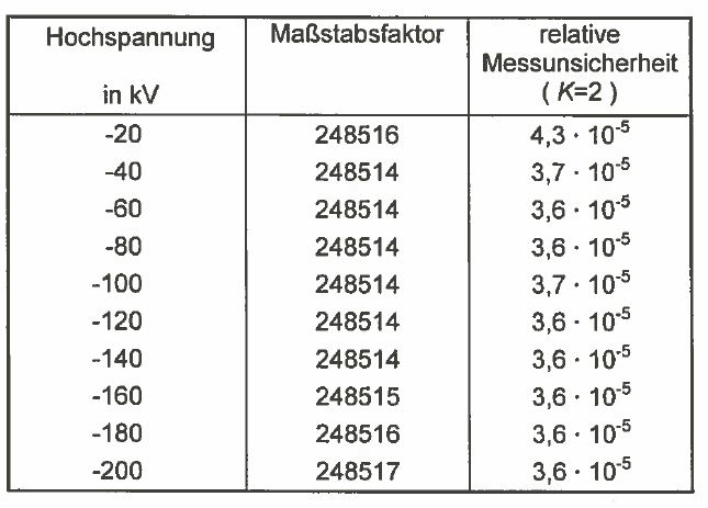
Sebastian | DAQ | Teilungsverhältnis Ohmlabs HVS250 |
Hochspannung Maßstabsfaktoren

-140 kV >>> 248514
-160 kV >>> 248515 |
| Attachment 1: Bericht_PTB_verbesserter_Teiler_2018.pdf
|
|
| Attachment 2: Maßstabsfaktoren.JPG
|
|
|
31
|
Thu Feb 20 13:51:04 2025 |
Denise, Sebatian | DAQ | DAQ Channelliste |
|
TDC Channels |
| |
Channel # | Kanalbelegung
| |
0 | Laser busy Kr
| |
1 | Next Laserstep Kr
| |
2 |
| |
3 |
| |
4 | PMT Mitte
| |
5 | PMT Nord
| |
6 | XUV Anode
| |
7 |
| |
8 |
| |
9 |
| |
10 | Bunch HF (common stop)
| |
11 | Shutter auf
| |
12 | Shutter zu
| |
13 | PD NW / 89
| |
14 | PD SW / 89
| |
15 | AFG rep / 89
|
|
Scaler Channels |
| |
Channel # | Kanalbelegung
| |
16 | DC Trafo
| |
17 | Injection
| |
18 | U-ecool
| |
19 | I-ecool
| |
20 | P-gun
| |
21 | P-coll
| |
22 | common stop (Bunch HF)
| |
23 | 1MHz clock
| |
24 | Extraktion
| |
25 | Shutter (10kHz)
| |
26 |
| |
27 |
| |
28 |
| |
29 |
| |
30 |
| |
31 |
|
|
|
30
|
Thu Feb 20 13:37:30 2025 |
Denise, Sebastian | DAQ | CFD Schwellen DAQ |
Schwellen fuer den CFD N842 (lascool)
Lasereinstellungen dabei waren: 0.5 Skalenteile -> 115ps Pulse
3.56654MHz Reprate
Stab (3.FV) wurde auf 1.2A betrieben
mit dem PBSc wurdee eine Laserleistung von 50mW in den ESR geschickt
|
CFD Channel | Kanalbelegung | Schwelle
| |
0 | PD NW | 14
| |
1 | PD SW | 14
| |
2 | Shutter auf | 20
| |
3 | Shutter zu | 20
| |
4 | AFG rep | 5
|
|
|
29
|
Thu Feb 20 00:45:00 2025 |
Danyal | General | Doppler width of M1 transition |
According to Paul Indelicato

transition 3P1 -> 3P0  in 78Kr32+ :

A	2.48E+08	1/s   "transition rate"
t	4.03E-09	s     "lifetime 3P1"
dv	3.95E+07	Hz    "natural line width"
dE	1.63E-07	eV    "width in eV"

Now, if we assume a final dp/p (after electron cooling) of the ion beam of ~1E-5,
this corresponds to a longitudinal temperature of ~16000 K (~1.4 eV).
This implies a Doppler width of ~26 GHz (ION frame).

This is broader than the width of the laser pulse in the ION frame (between 4.4 and 23.4 GHz).

This, in turn, implies that we should "see" the transition if we make 0.0024 nm steps in the UV (LAB frame).
The transition would then be something like 2-3 steps wide.

If we use this stepsize, and scan from 257.175 nm to 257.675 nm (LAB frame), we need 207 steps.

If one step takes 1 minute (using 1 ESR cycle and fixed laser wavelength per cycle), one scan takes ~3.5 hours !
I think that is too long.

For this procedure, the ESR cycle (injection -> next injection) must be faster.
Also the time for the laser to change the wavelength must be fast, but that should be OK.
We should try to get to sth. like 1 hour per scan. |
|
28
|
Mon Feb 17 13:49:20 2025 |
Denise | General | Frequenzbreiten Ionensystem |
Berechnung der Frequenzbreiten des Lasers im Ionensystem
Werte für die Frequezbreiten des Lasers aus Dissertation Benedikt Langfeld übernommen

v=0.644c

Pulsdauer = 115ps
Frequenzbreite (FWHM) = 10.87GHz
Frequenzbreite Ionensystem = 23.36GHz

Pulsdauer = 240ps
Frequenzbreite (FWHM) = 4.19GHz
Frequenzbreite Ionensystem = 9.00GHz

Pulsdauer = 400ps
Frequenzbreite (FWHM) = 2.82GHz
Frequenzbreite Ionensystem = 6.06GHz

Pulsdauer = 735ps
Frequenzbreite (FWHM) = 2.05GHz
Frequenzbreite Ionensystem = 4.41GHz |
|
27
|
Fri Feb 14 16:41:54 2025 |
Sebastian | General | Verkabelung PD ESR |
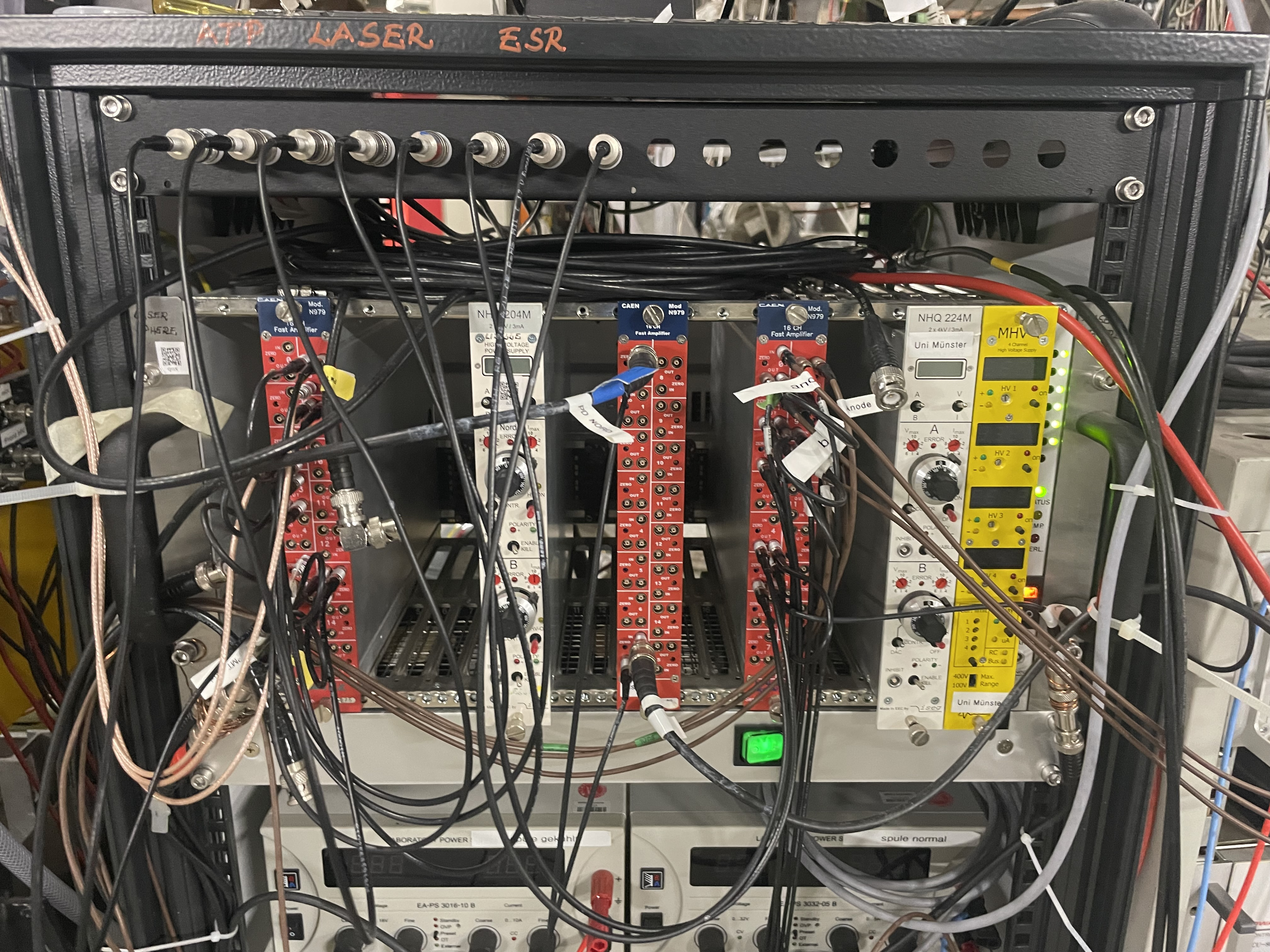
Verkabelung von den Photodioden im ESR. Sind auch gelabelt.

PD gehen zuerst einmal in den FAMP (10x Verstärkung)

PD NW -> ESR Panel 4
PD SW -> ESR Panel 7

XUV LED -> ESR Panel 8 |
| Attachment 1: IMG_8368.jpeg
|
|
|
26
|
Fri Feb 14 16:24:22 2025 |
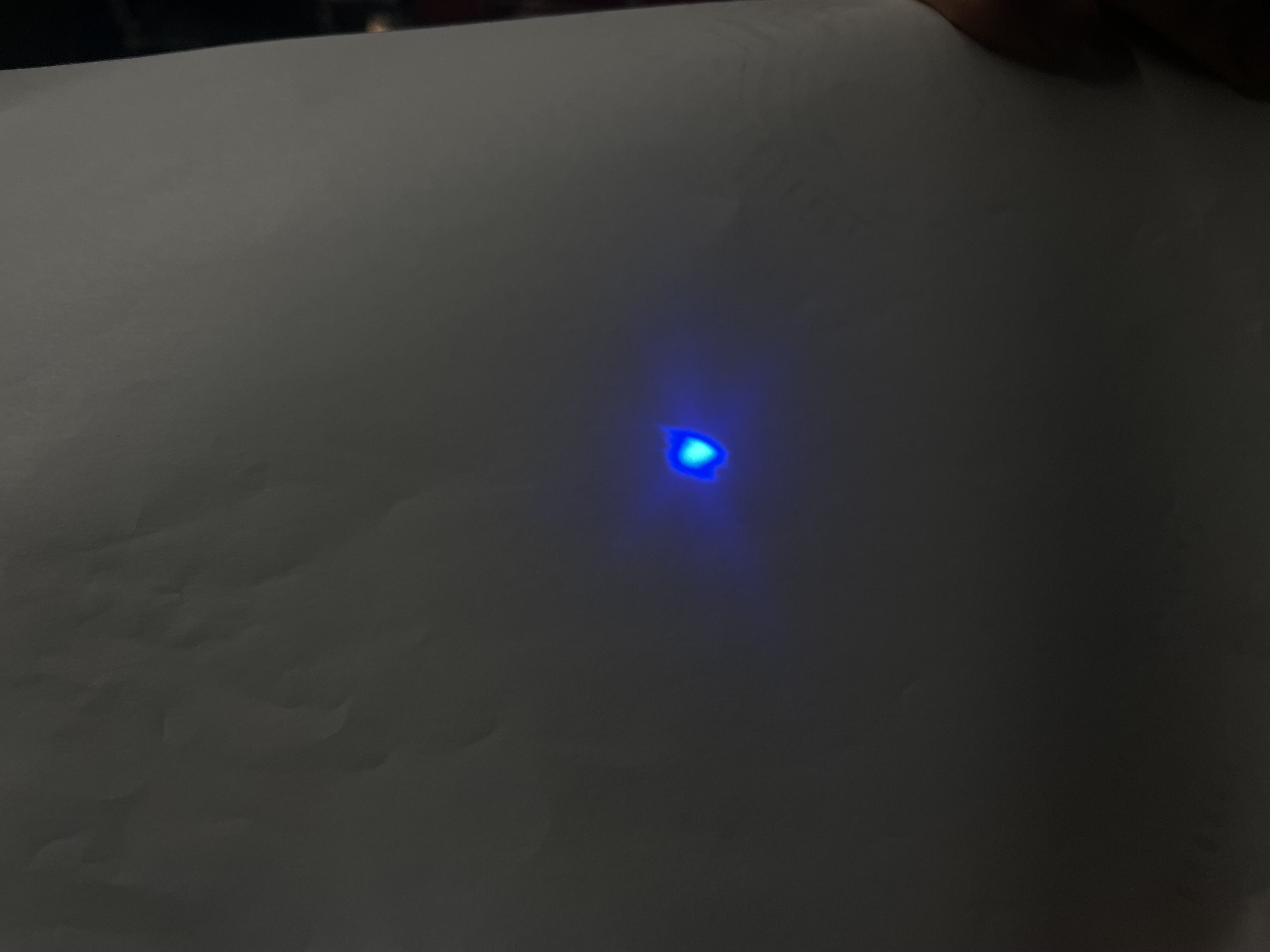
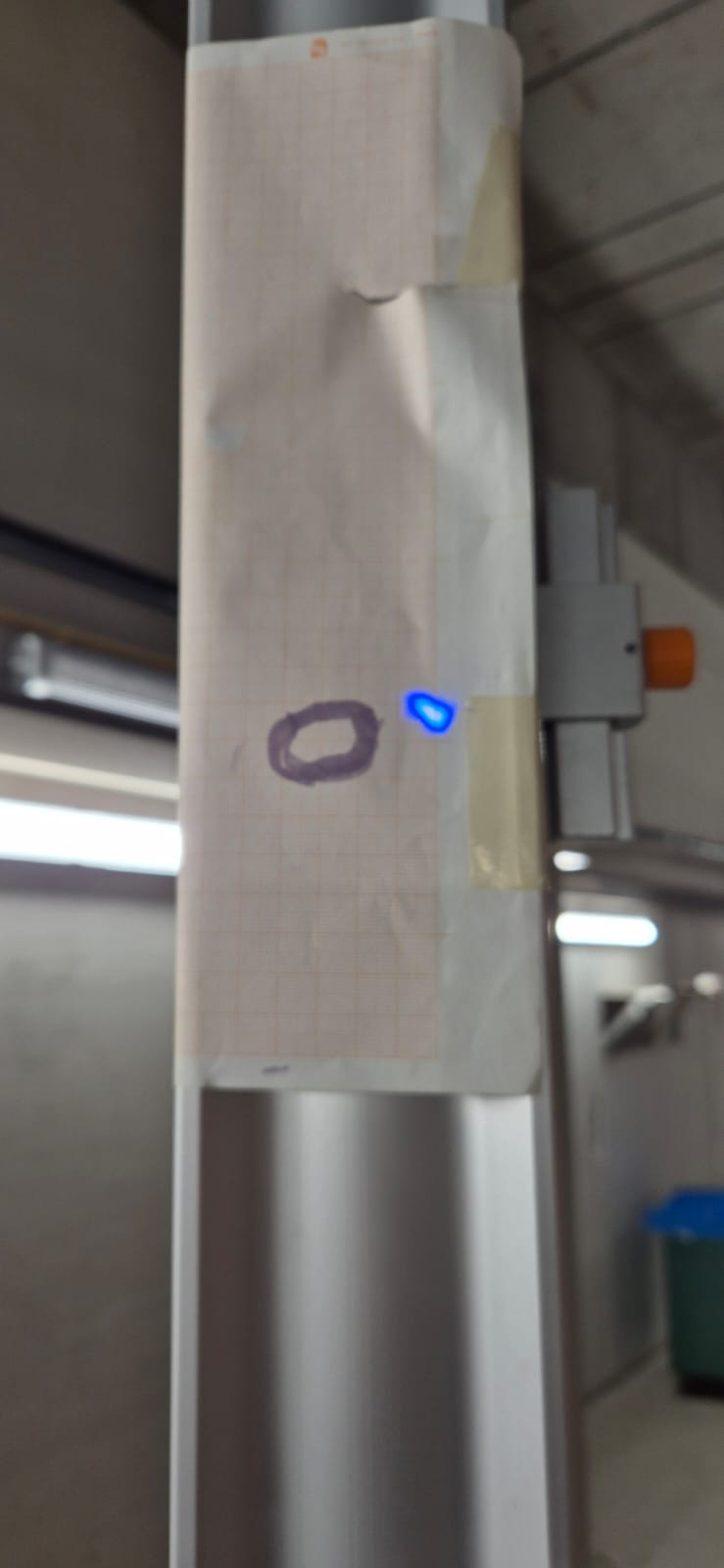
Denise | General | Strahlprofil UV im ESR |
Erstes Bild ist das Strahlptofil in Höhe des Nord
towers.
Zweites Bild (mit Millimeterpapier) und Video zeigt
das Strahlprofils etwa in Höhe des XUV Detektors im
ESR. Das Zittern ist dabei durch anstoßen am Nord
Tower entstanden, wichtig hier zu sehen ist das
„Atmen“ des Strahlprofils, welches dabei allerdings
örtlich fest bleibt. |
| Attachment 1: IMG_8360.jpeg
|
|
| Attachment 2: 796a74f2-ec76-4396-82e5-9d3209b36612.jpeg
|
|
| Attachment 3: 0bbd839a-f6cf-4fa4-a5a4-71d0c84044fa.mov
|
|
25
|
Thu Feb 13 12:56:01 2025 |
Danyal | General | ESR access - monday (whole day) 8-18 hr |
|
|
24
|
Thu Feb 13 12:55:13 2025 |
Danyal | General | ESR access - tomorrow (Fri) 10:00 - 12:00 |
|