|
HOME
ESR
EXPERIMENTS
LABS etc
|
|
E121
E127
E132
E125
E143
laser_cooling_2021
E142
Ê128
E146
E0052
E0018
E0028
E0038
E0075
E0203_E0018
E0052_2025
E0281 - NEEC
|
| Nuclear hyperfine mixing in 229Th89+ |
Not logged in |
 |
|
|
|
Message ID: 31
Entry time: Wed Mar 23 16:58:33 2022
|
| Author: |
V. Hannen |
| Category: |
Detectors |
| Subject: |
Status copper mirror and XUV detectors |
|
|
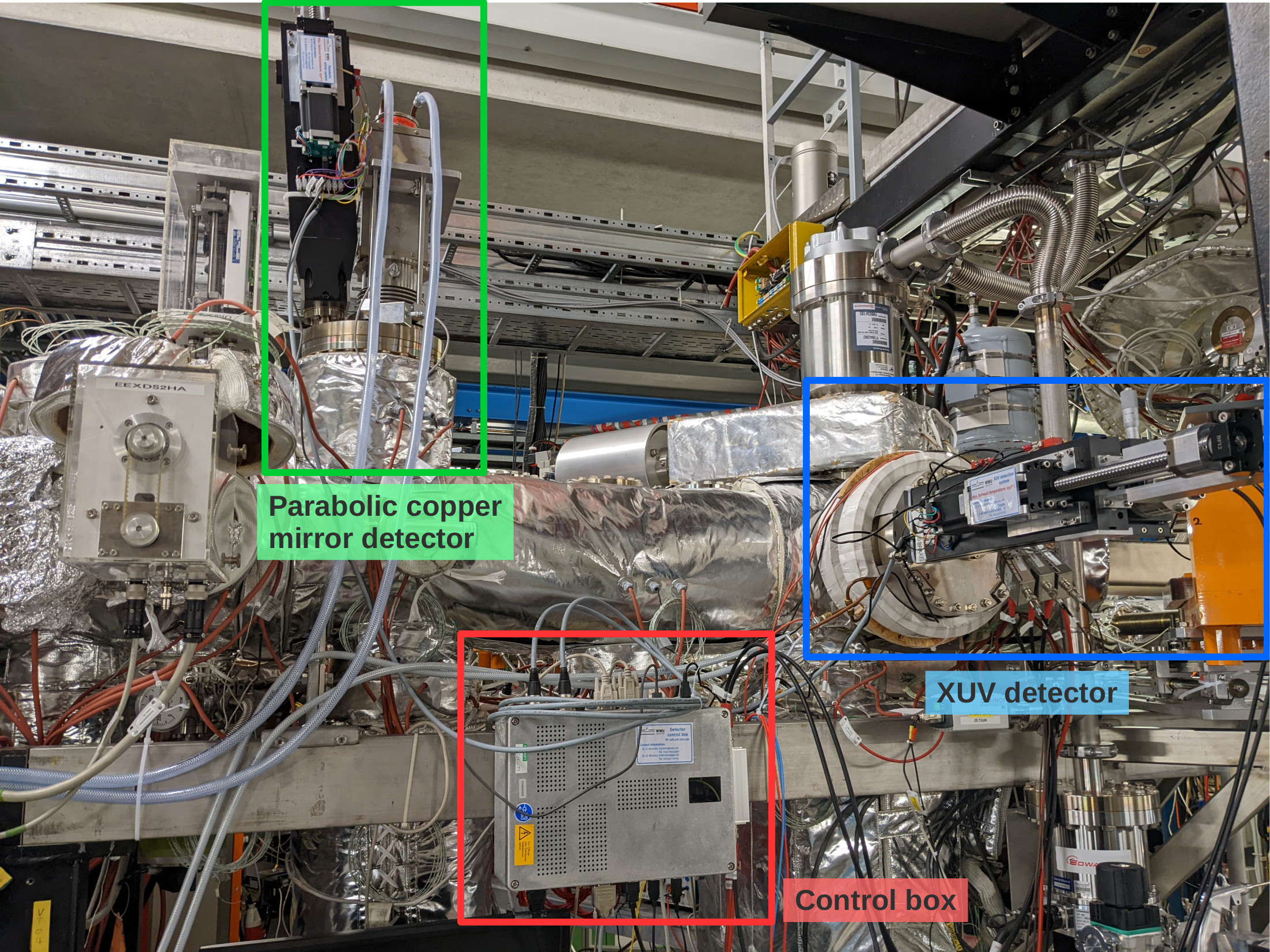
Over the past days, the parabolic copper mirror and XUV detectors haven been prepared and tested for the upcoming beamtime (see first attached photo for an overview of the detectors).
The positioning of the mirror and the cathode of the two detectors in their central positions in the beampipe have been adjusted. To reach this central position, the XUV cathode has to be moved 147 mm out of the parking position, while the parabolic mirror has to be moved by 173 mm. While the parabolic mirror will most probably always be driven the full pathlength to make maximum use of the Doppler shift of the emitted photons, the cathode will be placed somewhere in between parking and beam position to minimize background while still having a good detection efficiency.
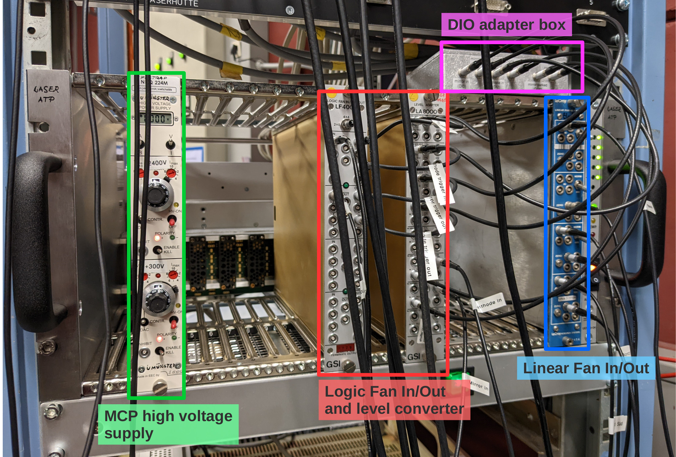
The MCP of the XUV detector is supplied with high voltage using an iseg 2 channel HV supply located in a NIM crate in the laser lab (see second photo). The required voltages are: +2400 V for the anode (upper channel) and +300 V for the MCP front (bottom channel).
The PMT of the copper mirror detector is supplied with HV by the same module as the PMTs on the new mirror chamber and has to be operated at a voltage of -1300 V.
The analog signals of both detectors are amplified by a factor 100 inside the ESR and patched through to the "Messhütte". For the MCP, the anode and MCP back signals are used (the MCP front signal is weak and noisy and doesn't give additional information). The MCP back signal has a positive polarity and is inverted in a linear Fan In/Out module in the NIM crate in the laser lab prior to discrimination.
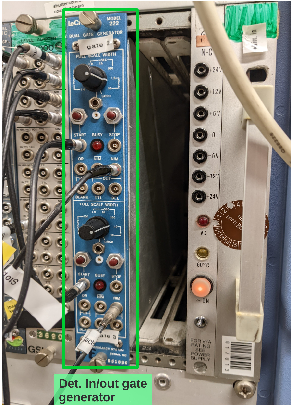
To trigger the movement of the copper mirror and the cathode from their respective parking positions to the measuring positions and back during each filling cycle of the ESR, two signals labeled "trigger in" and "trigger out" need to be provided from the ESR. These signals have to be connected to the "START" inputs of the gate generator in the Messhütte shown in the third photo. The upper channel processes the "trigger out" signal, the lower channel the "trigger in" signal. From the gate generator the signals are patched to the laser lab, where they are multiplied and converted to TTL in the NIM crate shown in photo 2, and transfered to the detector control box using the adapter on top of the crate. Automatically moving the detectors in and out only works when the control software is running and the "Automation" radio buttons are checked (see software manual in Elog entry 30).
Still to be done:
- connecting the analog signals to CFDs in the Messhütte and subsequently to the TDC inputs
- determining dark count rates when all pressure gauges in the straight section on the detector side of the ESR are switched off
- check influence of new ion getter pump on the XUV detector dark count rate.
Should we not be around and help is needed with these detectors call:
Volker Hannen - 0176 50129187
Ken Ueberholz - 01578 5999489 |
|

|
|

|
|

|