| ID |
Date |
Author |
Category |
Subject |
|
80
|
Sun Apr 3 13:05:08 2022 |
Carsten | Laser | Distance of Partilce detecotrs wr.t. to electron cooler |
As of Yuris post in the elog the positions (Info from H. Weick):

The postion of the particle counter behind the cooler is 21.6 m behind the middle of the cooler.
This correspond to 21.6m /108,4m = 1 / 5.02 of a full revolution (please check the present revolution frequency, i.e. for 2MHz, i.e. 500ns we have the signal approx 100ns after the ion is in the middle of the cooler).
If the detecot Nord would be used for bunch timing (only planned if detctor south is defect) the distance is half a ring + 21.4m, beind the center of the cooler, i.e. (54.2m+21.6m)/108.4m ~ 0.7 |
|
82
|
Sun Apr 3 18:41:11 2022 |
Konstantin and Rodolfo | Laser | Beam Position Stabilization |
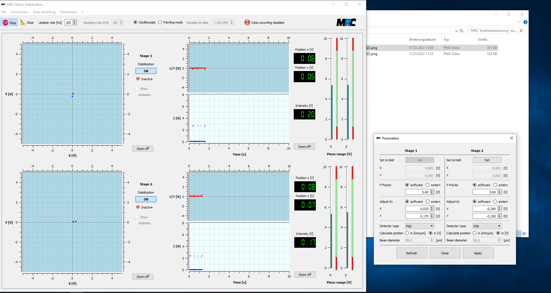
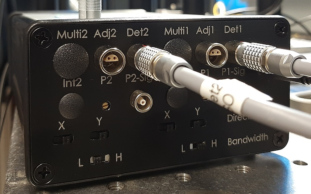
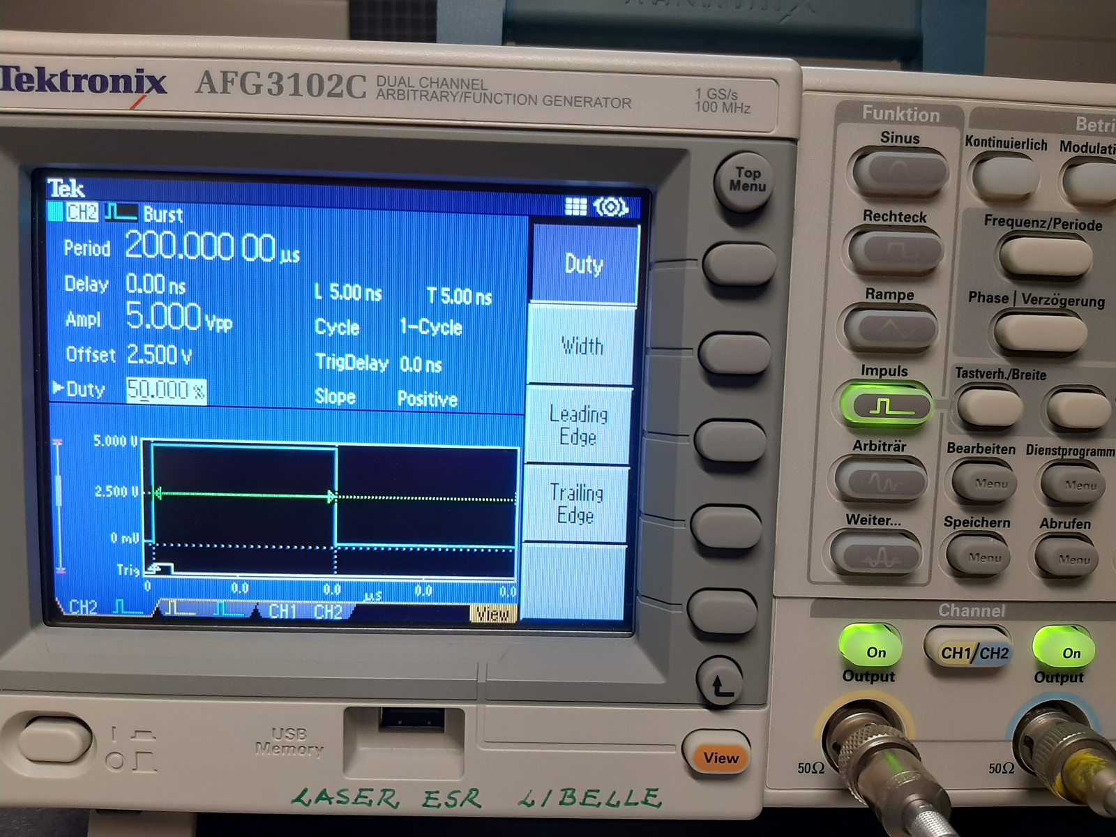
We (Konstantin and I) have optimized the TEM "laser-beam position stabilization".
- I took some pictures (screenshots) about the current setting*.
- In order to be able to move the laser position faster we increase the P-Factor of both stages to 5 (maximum value).
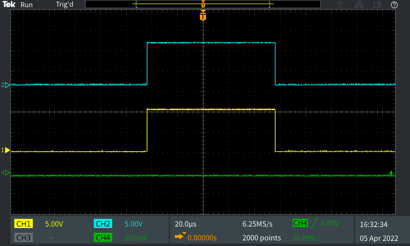
- In "TriggerSignals_f_MRC_04-04-2022" the fast PD defines the origin (t = 0 s). |
| Attachment 1: MRC_Konfiguration_MitMainAmp_03-04-2022.png
|
|
| Attachment 2: MRC-ControllerSetting_03-04-2022.jpg
|
|
| Attachment 3: FG_SettingsMRC_03-04-2022.jpg
|
|
| Attachment 4: TriggerSignals_f_MRC_04-04-2022.PNG
|
|
|
101
|
Tue Apr 5 20:16:13 2022 |
Rodolfo | Laser | Discriminator for HF reference signal |
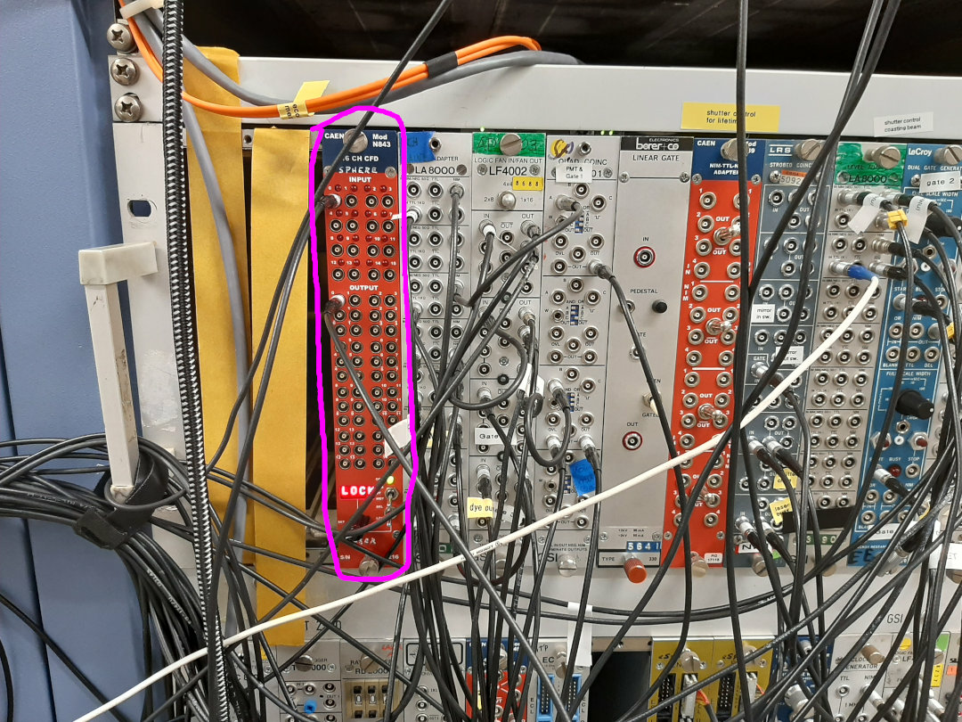
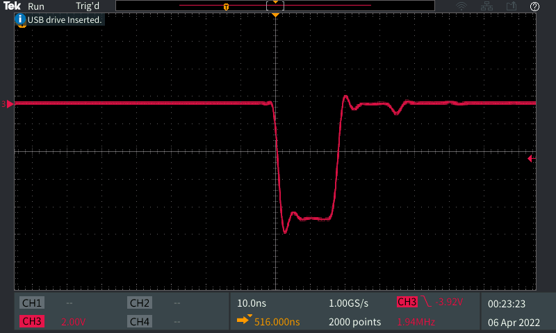
For the laser trigger we need to generate a few ns NIM-puls from the HF reference signal. Therefore we (Wilfried, Konstantin and me) have changed the constant fraction descriminator (CFD) to generate this kind of pulse.
- We are using now the module N843 from CAEN, see picture below. With this we could now produce ~20 ns long pulse.
- This signal is also used as STOP trigger for the VUPROMs |
| Attachment 1: CFD_für_HFSignal.jpg
|
|
| Attachment 2: Disc_HFSignal_05-04-2022.PNG
|
|
|
102
|
Tue Apr 5 20:58:53 2022 |
Wilfried | Laser | Trigger for Laser |
Electronic for the timing of the laser puls optimized. The problem with the broad photodiode histograms is solved.
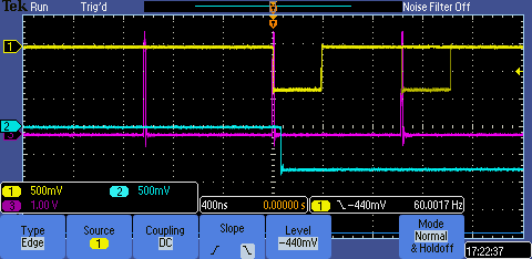
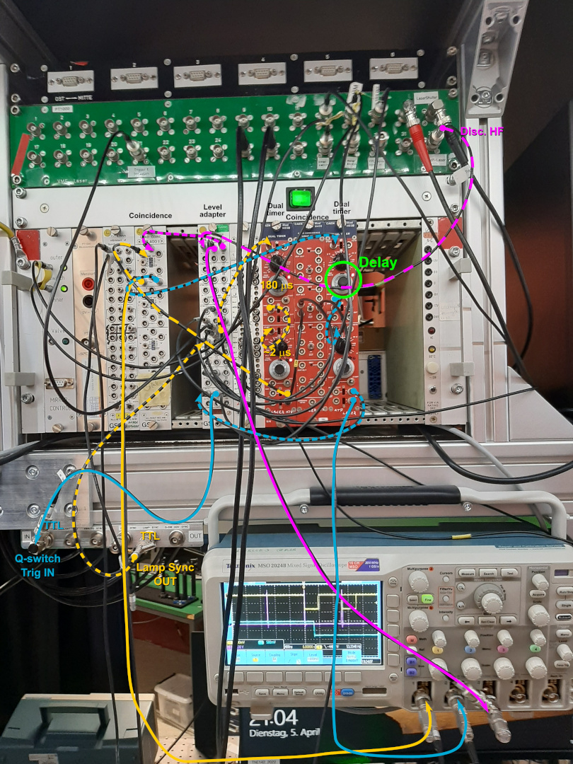
The photo of the oscilloscope picture shows in magenta the pulses from the (discriminated RF)/2, in yellow the pulses that are generated to open the Q-Switch. The latter are generated by the coincidence of the 30-Hz trigger (2 microsec long) to
allow for the Q-Switch to be fired. Within this period are usually 2 pulses from the RF and both generate a 100 ns long coincidence puls. The first one of those creates a 50 microsec long window (light blue) that is send to the Q-switch. The length
and the delay of this pulse can be changed. While the length is kept fixed, the delay can be changed in order to shift the arrival time of the laser pulse at the electron cooler to coincide with the ion bunch.
The problem of the wide photodiode histograms and the background was caused by a too large pulsewidth of the discriminated RF. The magenta pulses were about 100 ns long. Any pulse that arrives within a timespan between 99 and 0 ns before the 30-Hz
trigger of the Q-switch "allowance" will trigger a laser pulse immediately at the start of this trigger and therefore a jitter of up to 100 ns can occur. Therefore it is important that the CFD pulses are as short as possible, we set them to 20 ns
and the width of the photodiode histogram was just 3 bins wide (at the foot maybe 5 bins).
I (Rodolfo) just added the picture with the cabling configuration. The colors of cables match together with the colors show in the oscilloscope. |
| Attachment 1: TriggerForLaser_05-04-2022.PNG
|
|
| Attachment 2: TriggerLaser_Cabling.jpg
|
|
|
118
|
Thu Apr 7 00:15:11 2022 |
Patrick | Laser | Laser timing adjusted |
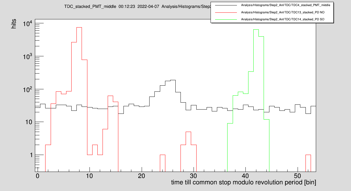
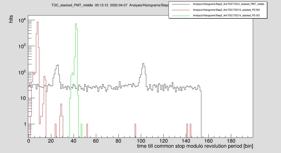
We have adjusted the laser timing using PMT-middle. Bunching freq. is 3.90362 MHz.
PD NO: 7.79
PD SO: 43.37
mean: 25.08
PMT middle: 25.02
Delta = 0.6 bins * 3.3 ns = 0.2 ns
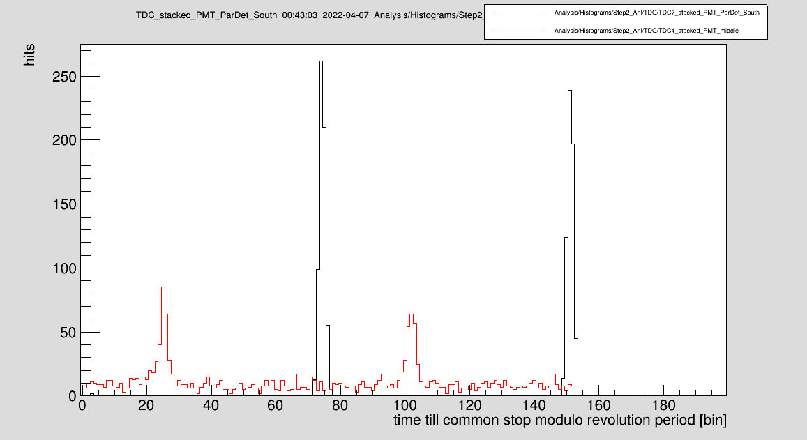
New injection:
PMT middle: 25.48 / 101.91
ParDet south: 74.31 / 151.31
ParDet south - PMT middle (furthest / closest distance) = 161.1 ns / 91.1 ns |
| Attachment 1: 220407-Laser-ion-timing.png
|
|
| Attachment 2: 220407-Laser-ion-timing-full-period.png
|
|
| Attachment 3: 220407-ParDetSO_PMT-middle.png
|
|
|
120
|
Thu Apr 7 01:19:05 2022 |
Patrick | Laser | Laser scanning |
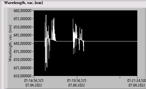
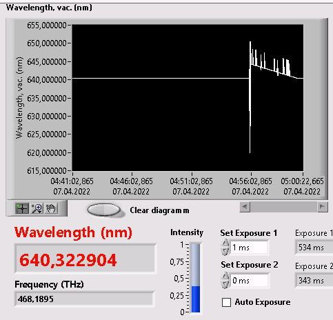
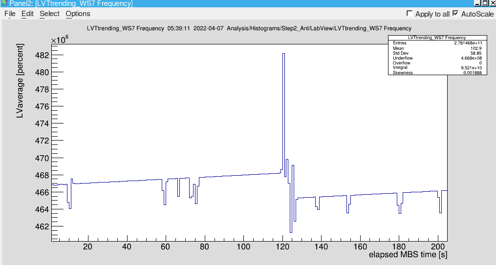
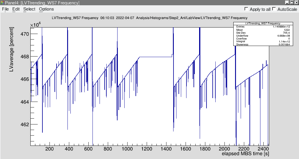
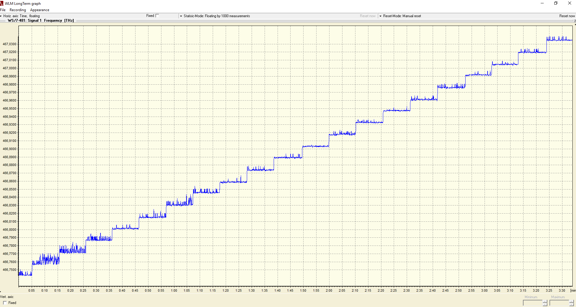
| We did some laser scans. The wavemeter shows spikes during scans. This may be just while the frequency changes. See picture. |
| Attachment 1: 2022-04-07_Wavemeter_during_scan.png
|
|
| Attachment 2: 2022-04-07_Wavemeter_during_scan2.png
|
|
| Attachment 3: 2022-04-07_Wavemeter_during_scan3.png
|
|
| Attachment 4: 2022-04-07_Wavemeter_during_scan4.png
|
|
|
136
|
Thu Apr 7 11:11:31 2022 |
Max, Sebastian | Laser | dye changed, pulse energy measurements |
We changed the dye at 10am.

We increased the pump power for the dye Laser to 480mJ (before 450mJ). New calibration factor is 29 for Quanta Ray monitor signal.

We get now 17mJ UV pulse energy after SHG. Pulse energy before was 14mJ. |
|
145
|
Fri Apr 8 00:06:37 2022 |
Patrick | Laser | Connection to the laser pc |
To login to the laser pc use the command
xfreerdp -g 1920x1080 -u atplaser atppc023.campus.gsi.de |
|
148
|
Fri Apr 8 02:14:05 2022 |
Wilfried | Laser | Laser timings adjusted |
Since we use the middle window as a reference for the laser pulse timing, the fact that the window is 2.25 m behind the target has to be taken into account. From here the ions have 10 ns less time of flight to the middle of the electron cooler than they need for half a revolution. The signals were still symmetrically aligned around the reference bunch as it was done yesterday. Therefore, the delay of the laser pulse was reduced by 10-ns on the oscilloscope, which led both photodiode histograms move 3 bins further to the right (towards larger times till common stop, since the pulse arrives earlier).
Since the RF frequency is turned down from ~ 1 MHz to ~ 400 kHz during injection/preparation, the laser does not fire reliably and the beam stabilization does not work very well during this period. This was solved by increasing the window in which the Q-Switch signal is accepted from 2 microseconds to 5 microsececonds. The laser is now firing regularly and with high power also during the preparation time and the beam position stabilization works very well. |
|
149
|
Fri Apr 8 03:54:39 2022 |
Patrick | Laser | Q-switch window |
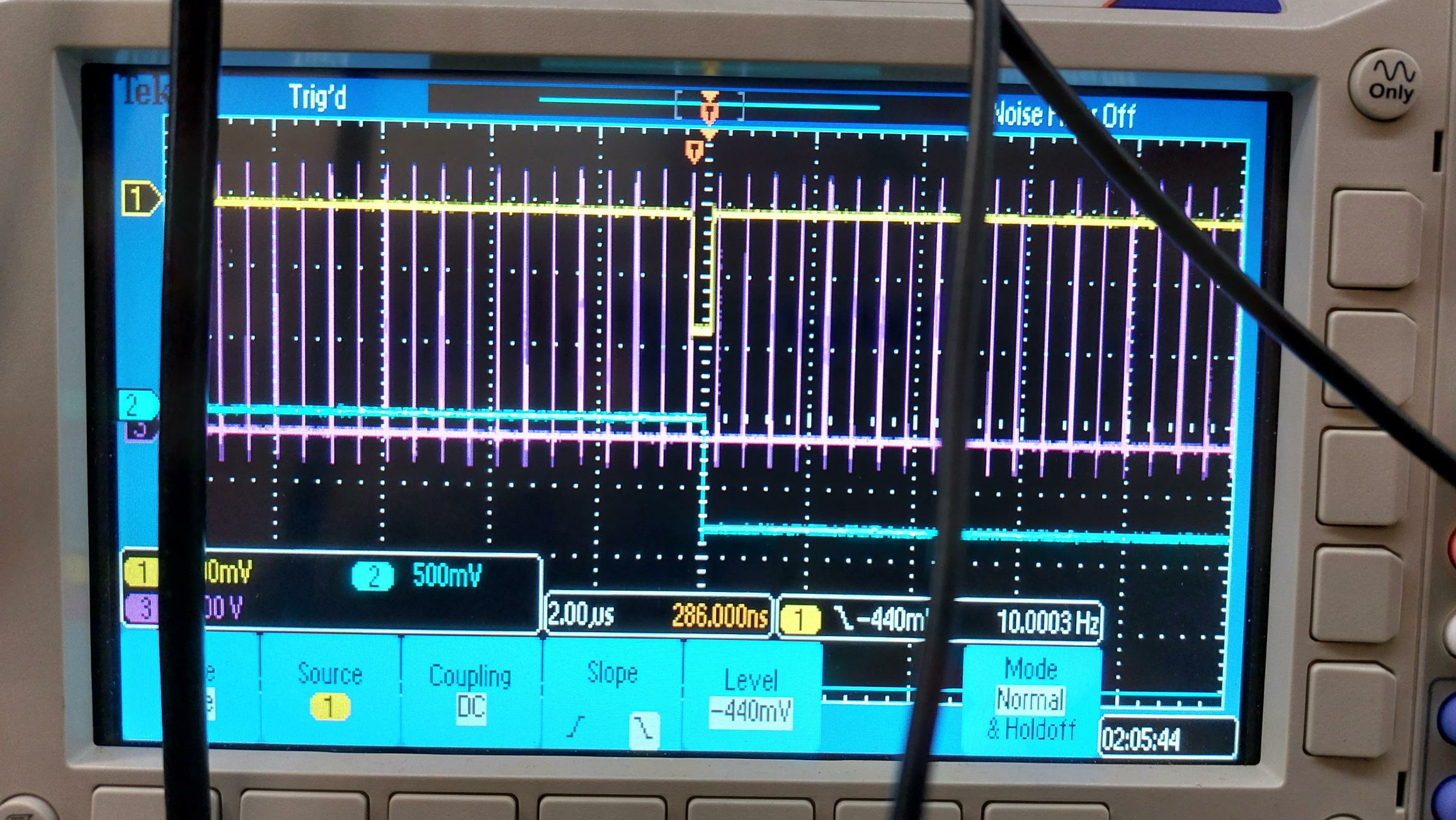
The solution of increasing the Q-switch window from 2us to 5us described in ID:148 fulfills its purpose, but the window is unstable.
We saw the laser jumping across the screen which was because the Laser had a lot of hickups.
The hickups come from the signal which determines the duration of the window.
This window "flickers". It gets very small, leaving no time for coincident events which fire the laser.
This is probably an issue with the NIM module.
Compare the picture below: The oscilloscope freezes and only the first of the yellow pulses is visible which should repeat and span 5us at the moment.
After looking at the different signals to trigger the laser on the oscilloscope, the laser does not fire anymore when used in the external trigger mode.
However, all signals are looking good and everything should be in the same state as before.
The internal Q-switch works as good as before. |
| Attachment 1: 2022-04-08_Q-switch_window.jpg
|
|
|
152
|
Fri Apr 8 08:17:52 2022 |
Sebastian | Laser | Laser Ext Trig is working |
We (Max, Kristian, Danyal, me) fixed the "external trigger" problem.

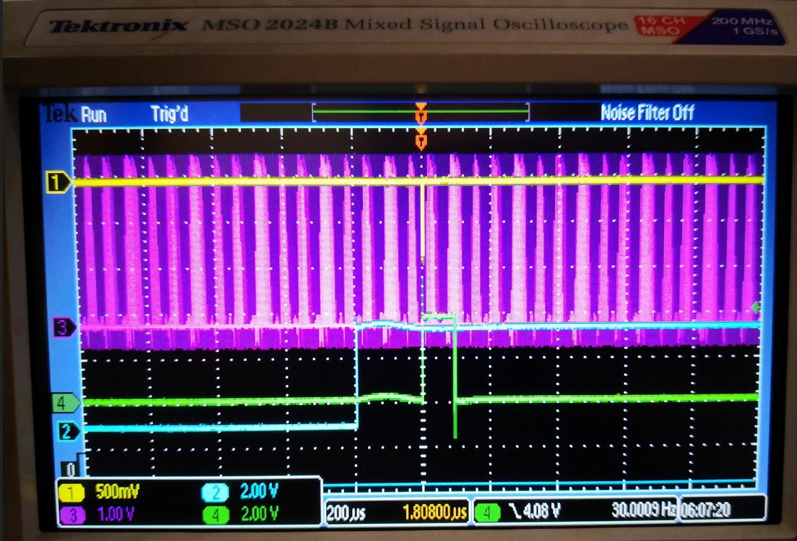
1.) The delay between lamp sync and Q-switch trigger was too long. The delay must be 200µs (3rd picture)!

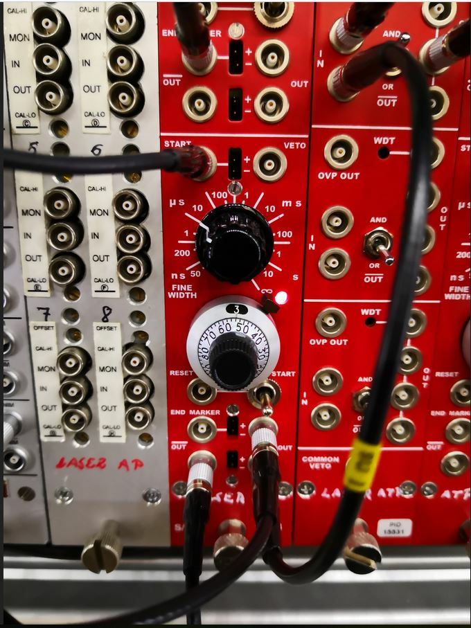
2.) The settings from the left Dual Timer (upper and lower part) in the ESR Laser Lab (above QuantaRay laser) were wrong and are now adjusted. Settings are depicted in the attached photos (1st and 2nd pic).

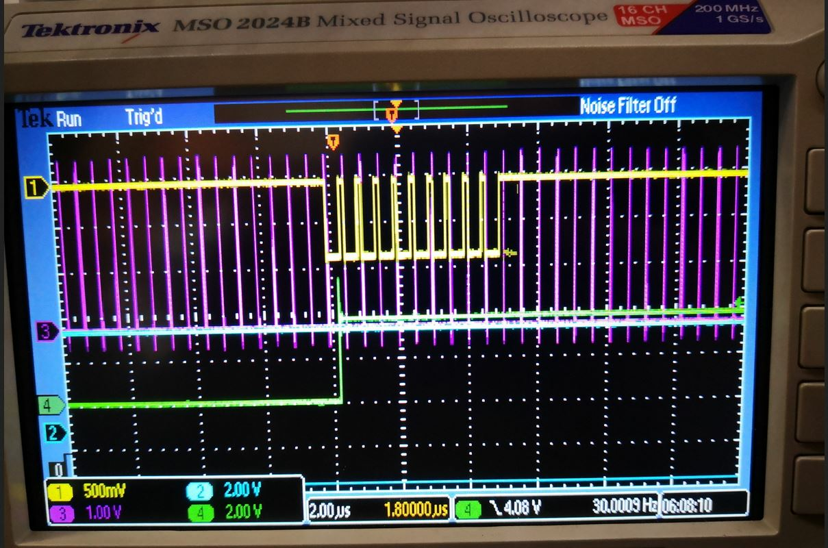
4th picture shows the pulse train of the pump laser. |
| Attachment 1: upperDualTimerSettings.JPG
|
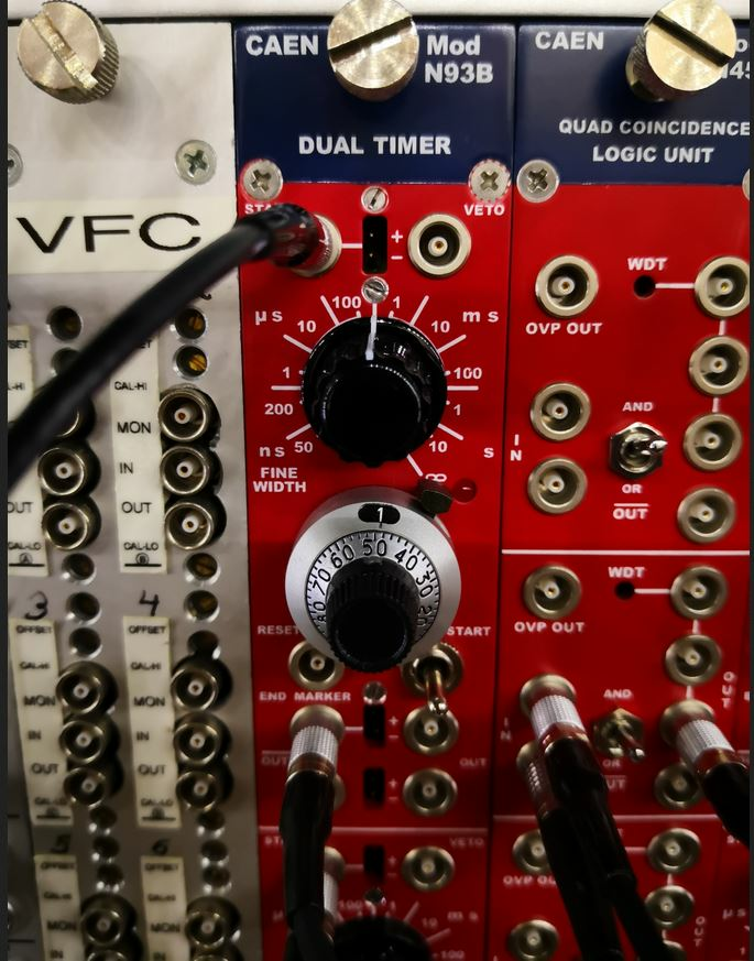
|
| Attachment 2: lowerDualTimerSettings.JPG
|
|
| Attachment 3: LampSyncToQSwitchTrig.JPG
|
|
| Attachment 4: TriggerPulseTrain.JPG
|
|
|
160
|
Fri Apr 8 11:16:57 2022 |
Kristian | Laser | Wavemeter |
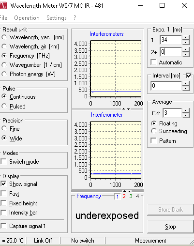
We changed the fiber to the wavemeter. The third fiber worked best and we could operate the WM at low exposure times, i.e., below the laser repetition rate. We used the neutral density filter to adapt the laser power that only one laser pulse is measured by the WM each time (Exposure time =34ms)

This way, there are no frequency jumps. The jitter is slighly different at each wavelength which was ~5GHz peak to peak.


We optimized the fiber coupler and slightly optimized the jitter to <4GHz. |
| Attachment 1: Wavemeter.PNG
|
|
| Attachment 2: Wavemeter2.PNG
|
|
|
180
|
Sat Apr 9 05:26:25 2022 |
Patrick | Laser | Wavemeter |
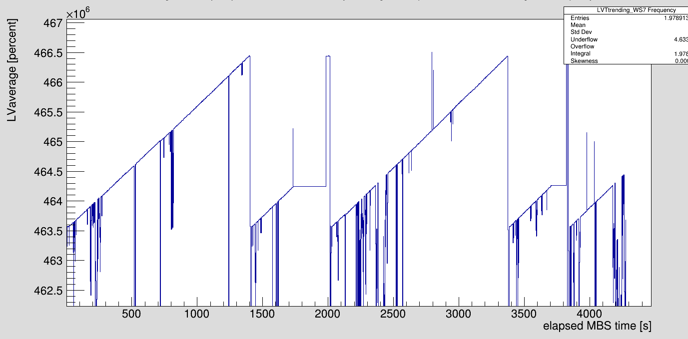
| The wavemeter still shows large spikes from time to time. The exposure time is still at 34ms. |
| Attachment 1: 2022-04-09_Wavemeter_during_scan5.png
|
|
|
182
|
Sat Apr 9 06:42:23 2022 |
Kristian | Laser | Laser step size |
We changed the laser step size to 0.002 nm which corresponds to 5.75 GHz. |
|
186
|
Sat Apr 9 16:55:19 2022 |
Rodolfo | Laser | |
16:15 I have changed the dye (of both oscillator and amplifier).
16:27 I have increased the pump energy (@ 532 nm) from 476 mJ to 507 mJ.
- UV output energy @ 322,8 nm: 12 mJ. (Before was at 9 mJ).
- New calibration factor is 160 for Quanta Ray monitor signal. |
|
188
|
Sat Apr 9 19:09:57 2022 |
Rodolfo | Laser | Optimization - Resonator of dye laser |
I have tuned a bit the resonator of the dye laser.
The total output energy after the main amplifier is 86 mJ (@ 645,6 nm)
The laser wavelength read by the wavemeter appears to be more stable (on the windows computer). We can see the histogram once the present scanning is finished. |
|
196
|
Sun Apr 10 08:53:26 2022 |
Kristian, Max | Laser | Timing verified |
timing is still good.

we checked the relative timing between laser and ions. the time difference between photodiodes, PMTs and particle detectors is still the same as original (see ELOG ID 169). The common stop of changed a slightly so that everything appears one bin later. |
|
197
|
Sun Apr 10 11:11:18 2022 |
Kristian, Max | Laser | additional WM readout |
since the WM readout still does not work reliably, I started a python script at atppc023 that saves timestamp and wavemeter frequency. in folder wavemeter at the desktop.

it is about 1 MB / h

Rename the old file and restart when you change the wavelength range. |
|
202
|
Sun Apr 10 15:29:53 2022 |
Rodolfo | Laser | Status - Laser system |
We have checked the laser system.
- The pump laser has ~ 23Mio shots. The total output energy has dropped to about 475 mJ. Maybe it is time to install new fresh flashlamps. In case the accelerator is going to have any mantainance tomorrow (Monday) then we can take the oportunity to exchange the flashlaps.
- The dye laser is pumped with 470 mJ (angle of lambda/2 plate = 112°).
- The energy after the second harmonic is 11,3 mJ @ 646 nm. We are using the Sarper's calibration table (635 nm - 646 nm) |
|
208
|
Mon Apr 11 11:05:35 2022 |
Sebastian, Kristian | Laser | Check laser power |
we checked the UV laser power at 10:15 am. It was only 8.5 - 9 mJ. Pumping power was 460 mJ, which is the maximum output of the current system. We should change the flashlamps soon |