| ID |
Date |
Author |
Category |
Subject |
|
162
|
Fri Apr 8 14:12:57 2022 |
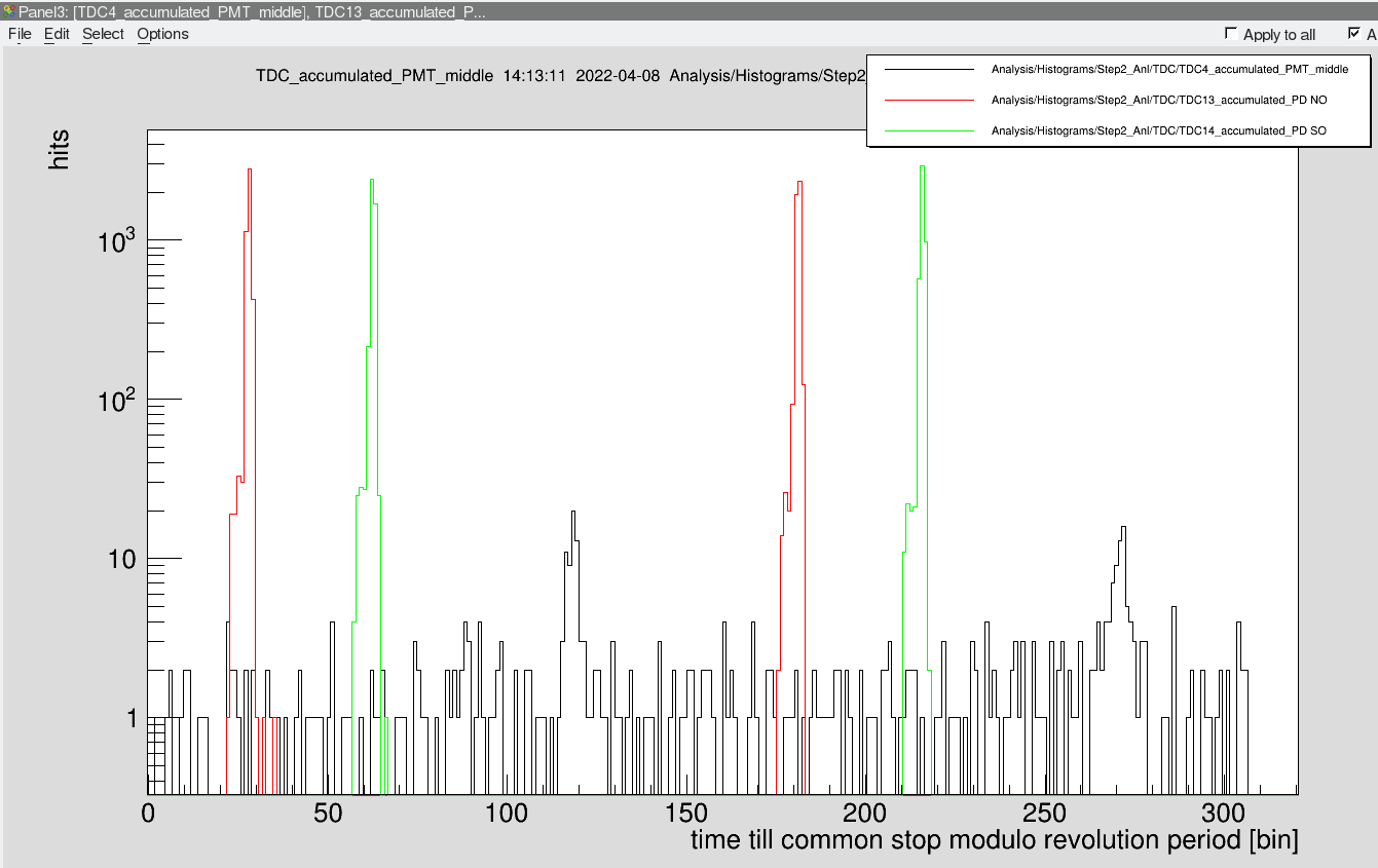
morning shift | DAQ | timing for h=1 |
The timing for h=1 has been set up

The time window is now twice as large as before!
This means that we see the same ion bunch twice.

(150 bins = 1 turn in the ESR)

The PMT signal is exactly in between two cycles + the extra flight time (3 bins = 10 ns) from target to PMT north. |
| Attachment 1: 2022-04-08_timing_h1_final.png
|
|
|
121
|
Thu Apr 7 02:32:29 2022 |
all on shift | Runs | First Scans 322-320nm |
Laser scanning from 322-320 steps 0.01nm/s
DAQ1: lxg1927:/data.local2/BeamTimeTh22/
DAQ2: lxg0155:/data.local2/E142/
LMD file name DAQ1:229Thor
LMD file name DAQ2:229Th
|
Time | SIS-intensity | cooler-HV | LMD-DAQ1 | LMD-DAQ2
| |
02.30 | ? | ? | Th227781-Th227784 | 0027-0028
| |
03.03 | 1.75e9 | 209648 | 7785-7787 | 0029-0030
| |
03:28 | 1.7e9 | 209648 | 7788 | 0031 (stopped during scan)
| |
Break - fixing cables, Elog ID: 125
| |
04:00 - problems with UNILAC, stopping for now.
| |
Apparently not so bad problems. we can continue.
| |
Mesytek PS of xuv-detector crashed, can only be restarted from inside the ESR by turning the crate on and off.
| |
05.20 | 1.23e9 | 209646 | 7791-7794 | 0035-0038
| |
05.52 | 1.5e9 | 209648 | 7795-7797 | 0039-0042
| |
06.24 | 1.5e9 | 209642 | 7798-7800 | 0043-0046 | 1 sec waiting at each laser frequency (dwell time 30)
| |
07.36 | xx e9 | 209 xx | 7803-7804 | 0047-0050 | problems with DAQ 1 and DAQ2
| |
07.52 | xx e9 | 209646 | 7805-7809 | 0051-0055 | DAQs started again | 5 sec waiting at each laser frequency (dwell time 150)
| |
08.30 | e9 | 209 xx | 7810-78 | 0056-00 | DAQs started again | 5 sec waiting at each laser frequency (dwell time 150)
| |
|
|
|
166
|
Fri Apr 8 15:39:36 2022 |
all | Runs | first data after timing set up |
started taking data again

started at 15:40
h=1

file names
229Th7821 DAQ 1  607 MB
229Th0082 DAQ 2  820 MB

stopped at 16:25


The laser was not really properly scanned.
This was mainly a test run to see if everything was working. |
|
75
|
Sun Apr 3 10:35:20 2022 |
Yuri (Sergey) | Accelerator | Dipole correction |
The ramp for moving the beam to the central orbit
To be inserted into manipulation, GE01MU1 (SC 5): 1.05969755 rad
This can be done only when one stays in the manipulation 5
Afterwards “Manipulieren” and not “An Geräte schicken” |
|
74
|
Sun Apr 3 10:28:25 2022 |
Yuri (Helmut Weick) | Accelerator | Distance cooler - detector |
Calculation from Helmut Weick
Distance e-cooler to particle detectors chamber:
“This is half of ESR plus distance target - detector. This even is on the web page”
54.28 m + 21.64 m |
|
131
|
Thu Apr 7 08:14:03 2022 |
Yuri & Danyal | General | 229Th89+ line in Schottky |
GLOBAL calculations for the "content" of the Th line in the Schottky spectrum
(380 MeV/u exit energy, equilibrium charge state distribution)

Actinium 9.9%  - bare

Thorium 42.4% - H-like

Protactinium 44.8% - He-like

Uranium 2.7% - Li-like |
|
68
|
Sat Apr 2 18:17:31 2022 |
Yuri | Accelerator | Photo-Identification |
Just a photo of the ID |
| Attachment 1: 9FFA52AA-1F75-470E-AD1B-E1A612A3F7D6.jpeg
|
|
|
69
|
Sat Apr 2 18:19:47 2022 |
Yuri | Accelerator | Scraping |
|
| Attachment 1: trim.3539D818-8003-4093-866E-2C4F619E614F.MOV
|
|
167
|
Fri Apr 8 15:42:20 2022 |
Yuri | Accelerator | Slits in the TE line |
At around 15:00, The slits in the TE line were changed to :
TE4DS5HL -12 mm -> -20 mm
TE5DSAH 0 mm -> +15 mm |
|
168
|
Fri Apr 8 15:45:24 2022 |
YL | | Spectrum manipulation 5 |
See attached |
| Attachment 1: IMG_3027.JPG
|

|
|
102
|
Tue Apr 5 20:58:53 2022 |
Wilfried | Laser | Trigger for Laser |
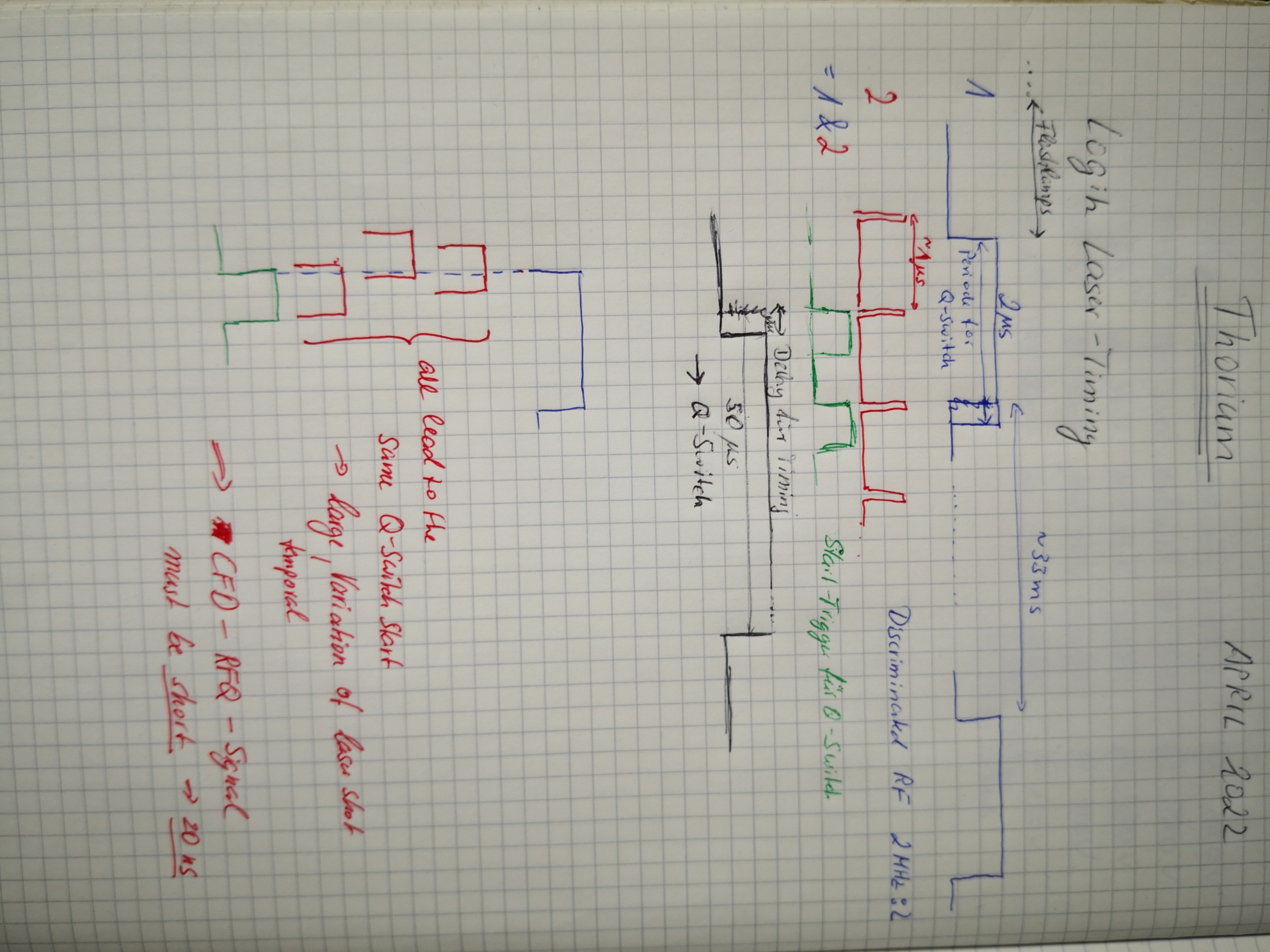
Electronic for the timing of the laser puls optimized. The problem with the broad photodiode histograms is solved.
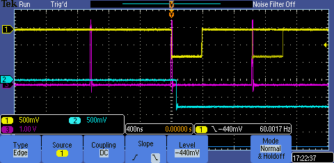
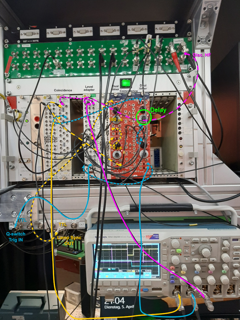
The photo of the oscilloscope picture shows in magenta the pulses from the (discriminated RF)/2, in yellow the pulses that are generated to open the Q-Switch. The latter are generated by the coincidence of the 30-Hz trigger (2 microsec long) to
allow for the Q-Switch to be fired. Within this period are usually 2 pulses from the RF and both generate a 100 ns long coincidence puls. The first one of those creates a 50 microsec long window (light blue) that is send to the Q-switch. The length
and the delay of this pulse can be changed. While the length is kept fixed, the delay can be changed in order to shift the arrival time of the laser pulse at the electron cooler to coincide with the ion bunch.
The problem of the wide photodiode histograms and the background was caused by a too large pulsewidth of the discriminated RF. The magenta pulses were about 100 ns long. Any pulse that arrives within a timespan between 99 and 0 ns before the 30-Hz
trigger of the Q-switch "allowance" will trigger a laser pulse immediately at the start of this trigger and therefore a jitter of up to 100 ns can occur. Therefore it is important that the CFD pulses are as short as possible, we set them to 20 ns
and the width of the photodiode histogram was just 3 bins wide (at the foot maybe 5 bins).
I (Rodolfo) just added the picture with the cabling configuration. The colors of cables match together with the colors show in the oscilloscope. |
| Attachment 1: TriggerForLaser_05-04-2022.PNG
|
|
| Attachment 2: TriggerLaser_Cabling.jpg
|
|
|
148
|
Fri Apr 8 02:14:05 2022 |
Wilfried | Laser | Laser timings adjusted |
Since we use the middle window as a reference for the laser pulse timing, the fact that the window is 2.25 m behind the target has to be taken into account. From here the ions have 10 ns less time of flight to the middle of the electron cooler than they need for half a revolution. The signals were still symmetrically aligned around the reference bunch as it was done yesterday. Therefore, the delay of the laser pulse was reduced by 10-ns on the oscilloscope, which led both photodiode histograms move 3 bins further to the right (towards larger times till common stop, since the pulse arrives earlier).
Since the RF frequency is turned down from ~ 1 MHz to ~ 400 kHz during injection/preparation, the laser does not fire reliably and the beam stabilization does not work very well during this period. This was solved by increasing the window in which the Q-Switch signal is accepted from 2 microseconds to 5 microsececonds. The laser is now firing regularly and with high power also during the preparation time and the beam position stabilization works very well. |
|
164
|
Fri Apr 8 14:43:50 2022 |
Wilfried | DAQ | laser timing - Q-switch start |
below are my notes concerning laser timing / Q-switch start |
| Attachment 1: IMG_20220408_143753_resized_20220408_023840170.jpg
|
|
|
222
|
Tue Apr 12 21:56:54 2022 |
Volker, David, Pierre-Michel & Danyal, Alexandre, Sebastian | General | new laser wavelength scan range 321.62 - 321.10 nm |
New wavelength scan range is 321.62 - 321.10 nm. Before the new scan range (compare old scan range in Entry 215) was applied,
the cooler settings were slightly modified. Current was changed from 50 mA to 40 mA, correction voltage was changed from 3943 V to 3948 V. Additionally, the positions
of scraper NA was changed from -10 mm to -8 mm and scraper NI from +10 mm to +8 mm.
|
Time | SIS-intensity | cooler-HV | LMD-DAQ2 file nr | LMD-DAQ1 file nr | scan range(nm) | step width(nm) | dwell time(s) | particles counted | comments
| |
21:57 | 1.55e9 | 209621 | 0226-0227 | 7962 | 321.62 - 321.10 | 0.002 | 5s | 7835 |
| |
22:54 | 1.4e9 | 209612 | 0228 | 7963 | 321.62 - 321.10 | 0.002 | 5s | 3326 | PMT south voltage reduced to 2400 V before run, Threshold now 80, Cooler Voltage changed to 209628 V at 23:19
| |
23:45 | 2.0e9 | 209628 | 0229-0230 | 7964 | 321.62 - 321.10 | 0.002 | 5s | 8560 |
| |
00:34 | 1.7e9 | 209626 | 0231 | 7965 | 321.62 - 321.10 | 0.002 | 5s | 7169 |
| |
01:29 | 1.1e9 | 209624 | 0232 | 7966 | 321.62 - 321.10 | 0.002 | 5s | 6412 |
| |
02:19 | 1.75e9 | 209626 | 0233 | 7967 | 321.62 - 321.10 | 0.002 | 5s | 7590 |
| |
03:06 | 1.6e9 | 209630 | 0234 | 7968 | 321.62 - 321.10 | 0.002 | 5s | 6329 |
| |
03:58 | 1.7e9 | 209629 | 0235-0236 | 7969 | 321.62 - 321.10 | 0.002 | 5s | 7710 |
| |
04:43 | 1.8e9 | 209629 | 0237 | 7970 | 321.62 - 321.10 | 0.002 | 5s | | Electron cooler went red @04:48
| |
05:48 | 1.5e9 | 209623 | 0238 | 7971 | 321.62 - 321.10 | 0.002 | 5s | 9420 |
| |
06:42 | 1.6e9 | 209616 | 0239 | 7972 | 321.62 - 321.10 | 0.002 | 5s | 8250 |
| |
07:32 | 1.7e9 | 209621 | 0240 | 7974 | 321.62 - 321.10 | 0.002 | 5s | 8840 | file 7943 was started accidentally too early and killed
| |
08:22 | 1.85e9 | 209622 | 0241 | 7975 | 321.62 - 321.10 | 0.002 | 5s | | ABORTED: laser did not start scanning
| |
08:33 | 1.90e9 | 209624 | 0242-243 | 7976 | 321.62 - 321.10 | 0.002 | 5s | 9955 |
| |
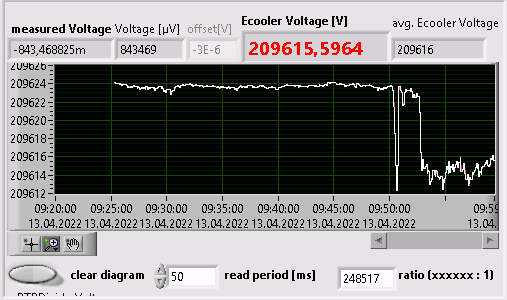
09:23 | 1.7e9 | 209624 | 0244-0245 | 7977 | 321.62 - 321.10 | 0.002 | 5s | 9021 | 09:50 Ecooler 12V drop for a few seconds; 9:52 again 12V E-cooler drop
| |
10:12 | 1.85e9 | 20962x | 0246 | 7978 | 321.62 - 321.10 | 0.002 | 5s | 8067 |
| |
11:10 | 1.7e9 | 209615 | 0247-248 | 7979 | 321.62 - 321.10 | 0.002 | 5s | 8905 |
| |
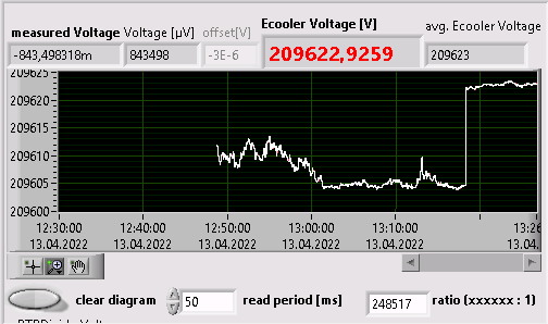
11:59 | 1.94e9 | 209612 | 0249-0250 | 7980 | 321.62 - 321.10 | 0.002 | 5s | 8203 | drop in E-cooler voltage of 8V at about 12:16 (before there was a slow increase from .612 to .620)
| |
12:48 | 2.0e9 | 209612 | 0251-0252 | 7981 | 321.62 - 321.10 | 0.002 | 5s | 8018 | E-cooler is not very stable (varies between .604 and .613) ; ~13:18 E-Cooler 18V jump to 209622V
| |
13:36 | 1.7e9 | 209621 | 0253 | 7982 | 321.62 - 321.10 | 0.002 | 5s | 8170 |
| |
|
|
| Attachment 1: Ecooler12VdropOn13_04_22_9_52am.png
|
|
| Attachment 2: Ecooler18VEcoolerJumpOn13_04_22_13_18pm.png
|
|
|
30
|
Wed Mar 23 16:16:42 2022 |
V. Hannen | Detectors | Control software for XUV and copper mirror detector |
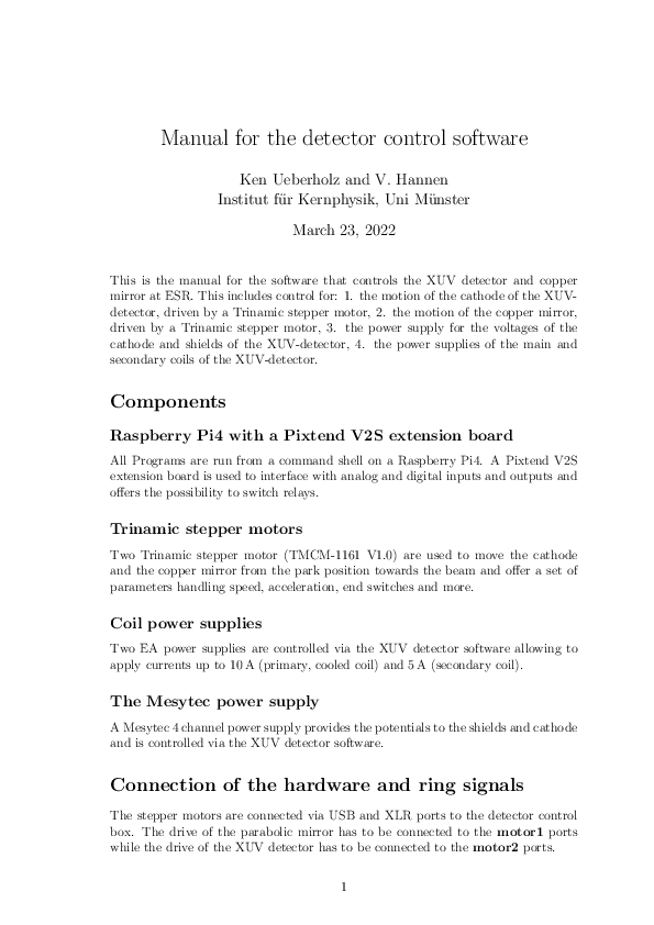
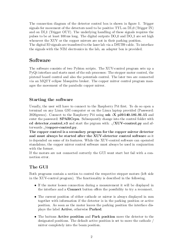
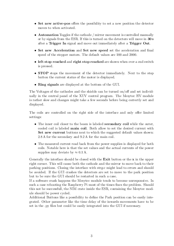
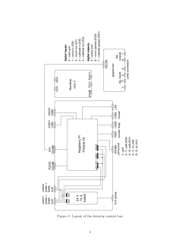
Attached you find a manual for the software used to control the movement of the XUV detector and the copper mirror detector.
The software is also used to set the electrode voltages and coil currents of the XUV detector. |
| Attachment 1: Manual.pdf
|
|
|
31
|
Wed Mar 23 16:58:33 2022 |
V. Hannen | Detectors | Status copper mirror and XUV detectors |
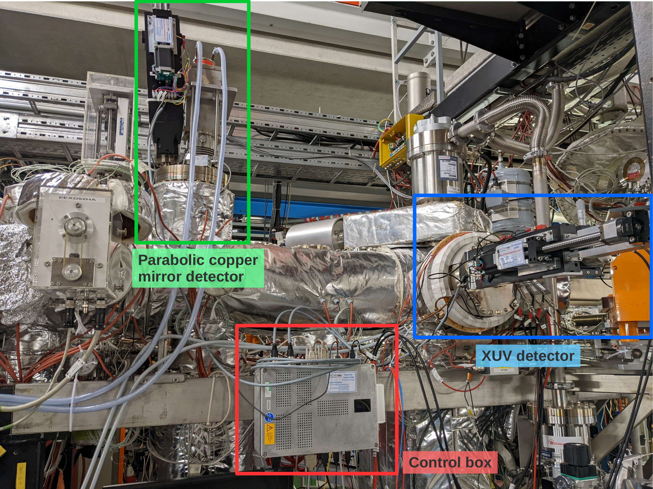
Over the past days, the parabolic copper mirror and XUV detectors haven been prepared and tested for the upcoming beamtime (see first attached photo for an overview of the detectors).
The positioning of the mirror and the cathode of the two detectors in their central positions in the beampipe have been adjusted. To reach this central position, the XUV cathode has to be moved 147 mm out of the parking position, while the parabolic mirror has to be moved by 173 mm. While the parabolic mirror will most probably always be driven the full pathlength to make maximum use of the Doppler shift of the emitted photons, the cathode will be placed somewhere in between parking and beam position to minimize background while still having a good detection efficiency.
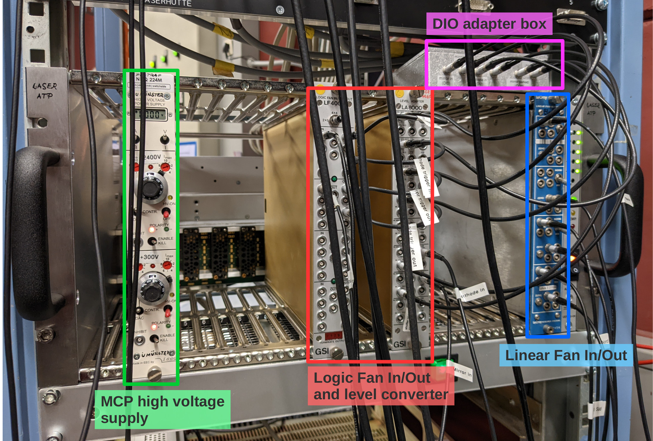
The MCP of the XUV detector is supplied with high voltage using an iseg 2 channel HV supply located in a NIM crate in the laser lab (see second photo). The required voltages are: +2400 V for the anode (upper channel) and +300 V for the MCP front (bottom channel).
The PMT of the copper mirror detector is supplied with HV by the same module as the PMTs on the new mirror chamber and has to be operated at a voltage of -1300 V.
The analog signals of both detectors are amplified by a factor 100 inside the ESR and patched through to the "Messhütte". For the MCP, the anode and MCP back signals are used (the MCP front signal is weak and noisy and doesn't give additional information). The MCP back signal has a positive polarity and is inverted in a linear Fan In/Out module in the NIM crate in the laser lab prior to discrimination.
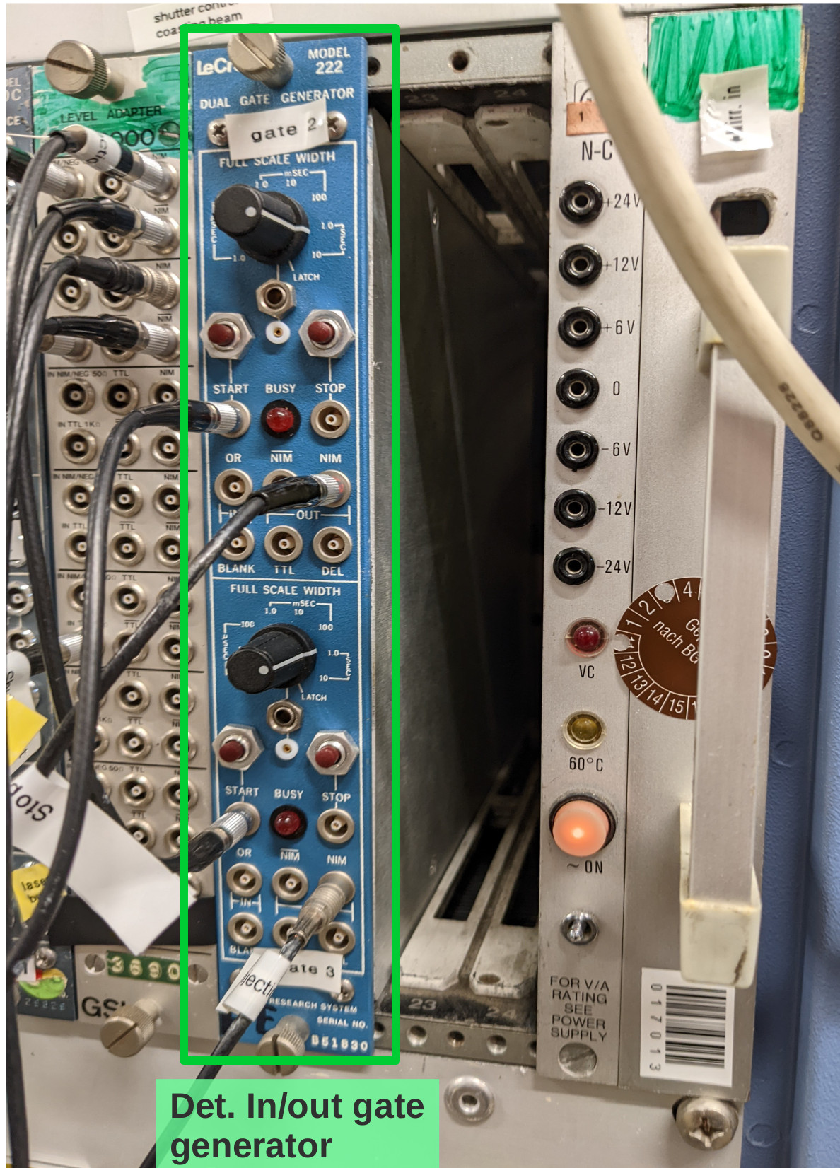
To trigger the movement of the copper mirror and the cathode from their respective parking positions to the measuring positions and back during each filling cycle of the ESR, two signals labeled "trigger in" and "trigger out" need to be provided from the ESR. These signals have to be connected to the "START" inputs of the gate generator in the Messhütte shown in the third photo. The upper channel processes the "trigger out" signal, the lower channel the "trigger in" signal. From the gate generator the signals are patched to the laser lab, where they are multiplied and converted to TTL in the NIM crate shown in photo 2, and transfered to the detector control box using the adapter on top of the crate. Automatically moving the detectors in and out only works when the control software is running and the "Automation" radio buttons are checked (see software manual in Elog entry 30).
Still to be done:
- connecting the analog signals to CFDs in the Messhütte and subsequently to the TDC inputs
- determining dark count rates when all pressure gauges in the straight section on the detector side of the ESR are switched off
- check influence of new ion getter pump on the XUV detector dark count rate.
Should we not be around and help is needed with these detectors call:
Volker Hannen - 0176 50129187
Ken Ueberholz - 01578 5999489 |
| Attachment 1: det-overview.jpg
|
|
| Attachment 2: laserlab-crate.jpg
|
|
| Attachment 3: trigger-module.jpg
|
|
|
150
|
Fri Apr 8 05:46:35 2022 |
V. Hannen | Detectors | High background rate in Cu PMT points to light leak in ESR or active pressure gauge |
The background rate of the Cu mirror PMT is only about 300 cps when the mirror is in the parking position but ca. 7000 cps when in the beam position, even if no beam is present in the ESR. This was noticed when we had an "empty injection" into the ring, causing the Cu mirror to drive into the beam position with no ions present.
This means either we have a light leak somewhere on the detector side of the ring, e.g. a not perfectly covered window, or we have a pressure gauge operating still to close by (during the LIBELLE experiment we turned off all pressure gauges on the detector side of the ESR not only in the straight section but also somewhat into the bends). This has to be checked the next time we can enter the ring. |
|
191
|
Sun Apr 10 03:56:56 2022 |
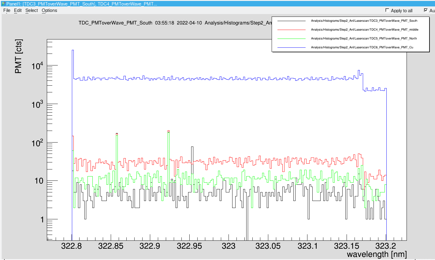
V. Hannen | Detectors | Low rate in PMT South |
PMT south shows a much lower count rate than observed in elog entry 170.
Yesterday the voltage on this PMT was increased to 2400 V and the threshold setting of the CAEN CFD to 90 units, (from 70 units before) however the low readout rate was already apparent both for the analog and the discriminated signal then.
Update Sun Apr 10, 21:45: on advice from D. Winters, increased the PMT voltage to 2500 V (max. the HV supply can do, the PMT could handle up to 3000 V) |
| Attachment 1: 2022-04-10_PMTs_over_wavel-03_56.png
|
|
|
119
|
Thu Apr 7 00:36:36 2022 |
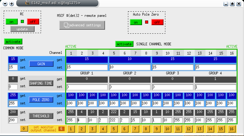
Uwe | DAQ | Threshholds and shaping Mesytec for ADC |
|
| Attachment 1: snapshot3.png
|
|
|
111
|
Wed Apr 6 15:19:29 2022 |
Svea, Shahab | Accelerator | 5s delay implemented before injection |
Operators have informed us that for better stability and operation (and cooperation with HHT), and after discussing with Sergey, they have introduced 5s delay "Wartezeit RESET" before every injection.

We have to observe this new behavior and in case it needs further optimizations, we have to inform the operators. |