| ID |
Date |
Author |
Category |
Subject |
|
33
|
Thu Mar 24 16:59:35 2022 |
Rodolfo | Laser | Photodiode signal SO |
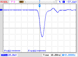
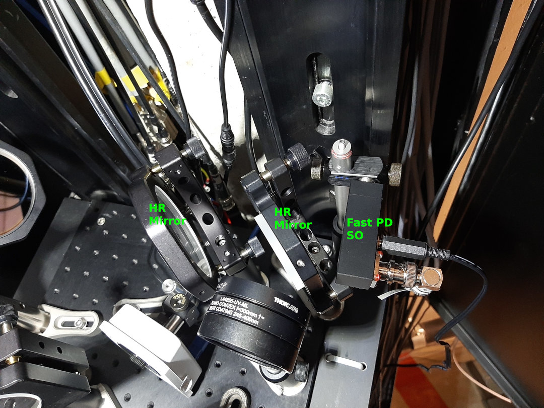
Fast Photodiode signal at the "SO-Bogen" (South-east arc).
- Average made over 250 samples.
- The photodiode is placed after two HR (high reflexion) mirrors. |
| Attachment 1: FastPD_SO_Signal_24-03-2022.jpg
|
|
| Attachment 2: FastPD_SO_24-03-2022.jpg
|
|
|
32
|
Thu Mar 24 13:27:47 2022 |
Rodolfo | DAQ | Disk space - LXG1297 |
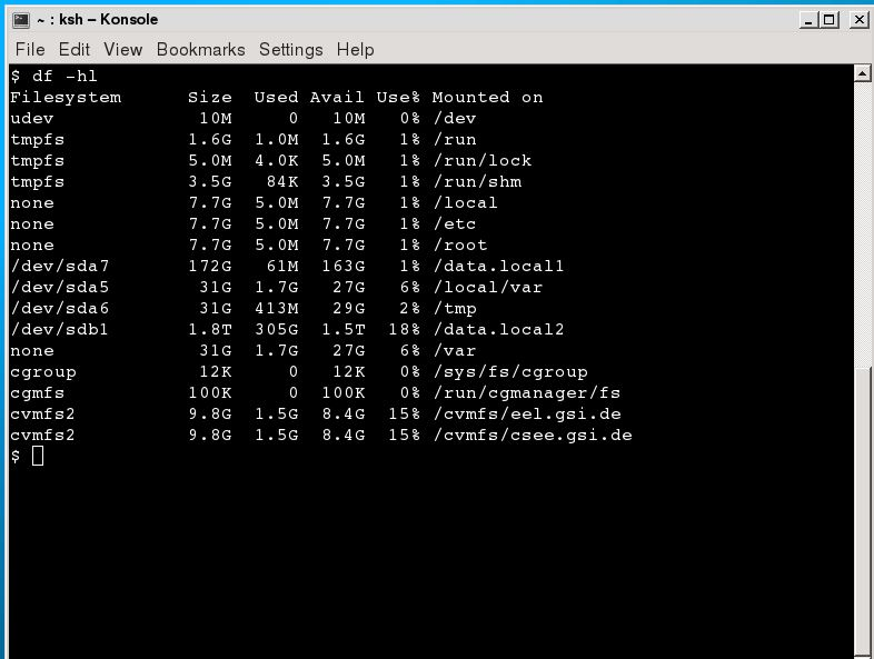
In our Linux computer (LXG1297: Laser spectroscopy) we have a Drive with 1.8 TB total disk space. 300 GB are at the moment in use, but I can clean this.
This computer is located in the "Atomphysik Messhütte". |
| Attachment 1: DiskSpace_lxg1297.JPG
|
|
|
31
|
Wed Mar 23 16:58:33 2022 |
V. Hannen | Detectors | Status copper mirror and XUV detectors |
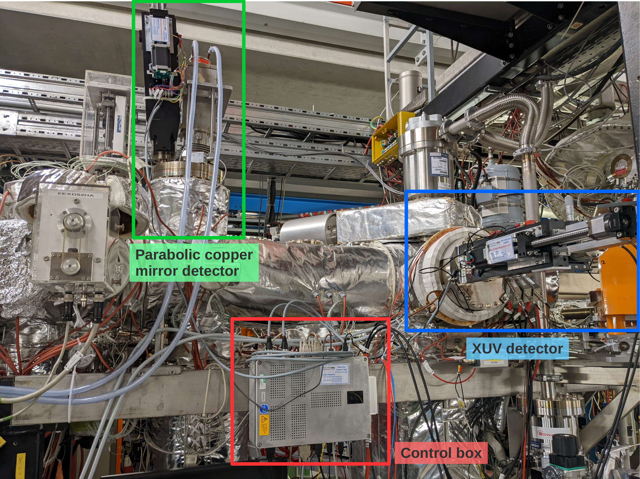
Over the past days, the parabolic copper mirror and XUV detectors haven been prepared and tested for the upcoming beamtime (see first attached photo for an overview of the detectors).
The positioning of the mirror and the cathode of the two detectors in their central positions in the beampipe have been adjusted. To reach this central position, the XUV cathode has to be moved 147 mm out of the parking position, while the parabolic mirror has to be moved by 173 mm. While the parabolic mirror will most probably always be driven the full pathlength to make maximum use of the Doppler shift of the emitted photons, the cathode will be placed somewhere in between parking and beam position to minimize background while still having a good detection efficiency.
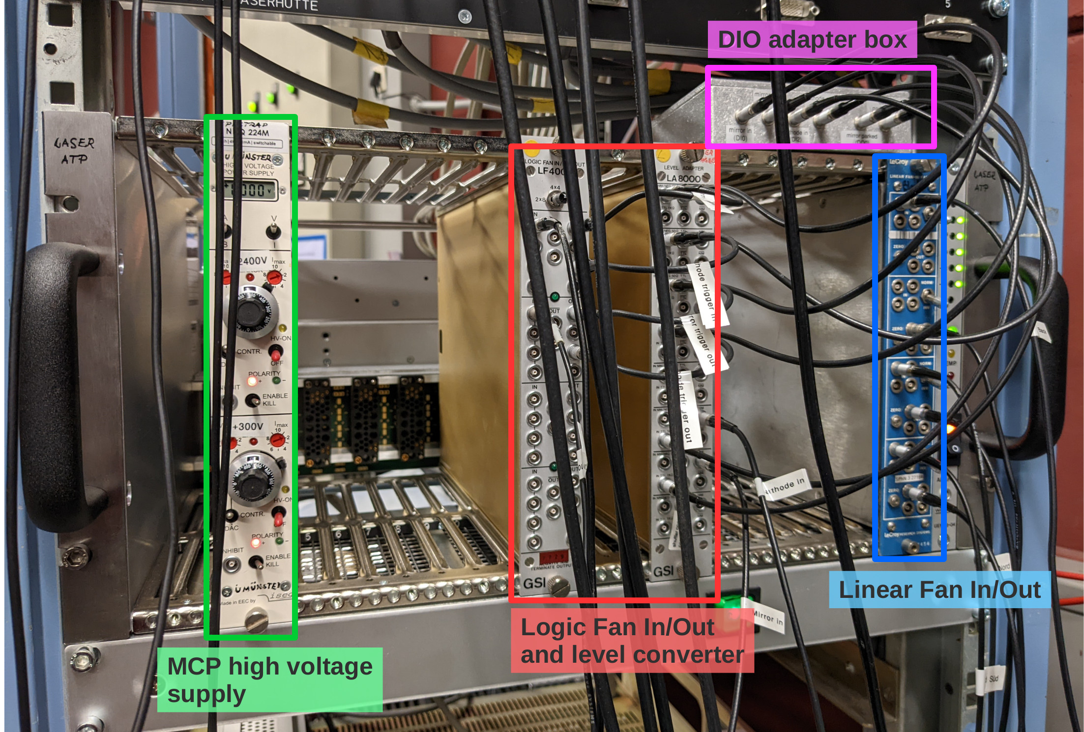
The MCP of the XUV detector is supplied with high voltage using an iseg 2 channel HV supply located in a NIM crate in the laser lab (see second photo). The required voltages are: +2400 V for the anode (upper channel) and +300 V for the MCP front (bottom channel).
The PMT of the copper mirror detector is supplied with HV by the same module as the PMTs on the new mirror chamber and has to be operated at a voltage of -1300 V.
The analog signals of both detectors are amplified by a factor 100 inside the ESR and patched through to the "Messhütte". For the MCP, the anode and MCP back signals are used (the MCP front signal is weak and noisy and doesn't give additional information). The MCP back signal has a positive polarity and is inverted in a linear Fan In/Out module in the NIM crate in the laser lab prior to discrimination.
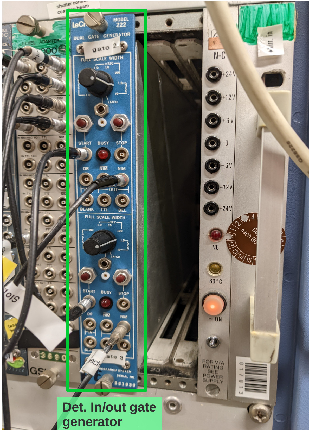
To trigger the movement of the copper mirror and the cathode from their respective parking positions to the measuring positions and back during each filling cycle of the ESR, two signals labeled "trigger in" and "trigger out" need to be provided from the ESR. These signals have to be connected to the "START" inputs of the gate generator in the Messhütte shown in the third photo. The upper channel processes the "trigger out" signal, the lower channel the "trigger in" signal. From the gate generator the signals are patched to the laser lab, where they are multiplied and converted to TTL in the NIM crate shown in photo 2, and transfered to the detector control box using the adapter on top of the crate. Automatically moving the detectors in and out only works when the control software is running and the "Automation" radio buttons are checked (see software manual in Elog entry 30).
Still to be done:
- connecting the analog signals to CFDs in the Messhütte and subsequently to the TDC inputs
- determining dark count rates when all pressure gauges in the straight section on the detector side of the ESR are switched off
- check influence of new ion getter pump on the XUV detector dark count rate.
Should we not be around and help is needed with these detectors call:
Volker Hannen - 0176 50129187
Ken Ueberholz - 01578 5999489 |
| Attachment 1: det-overview.jpg
|
|
| Attachment 2: laserlab-crate.jpg
|
|
| Attachment 3: trigger-module.jpg
|
|
|
30
|
Wed Mar 23 16:16:42 2022 |
V. Hannen | Detectors | Control software for XUV and copper mirror detector |
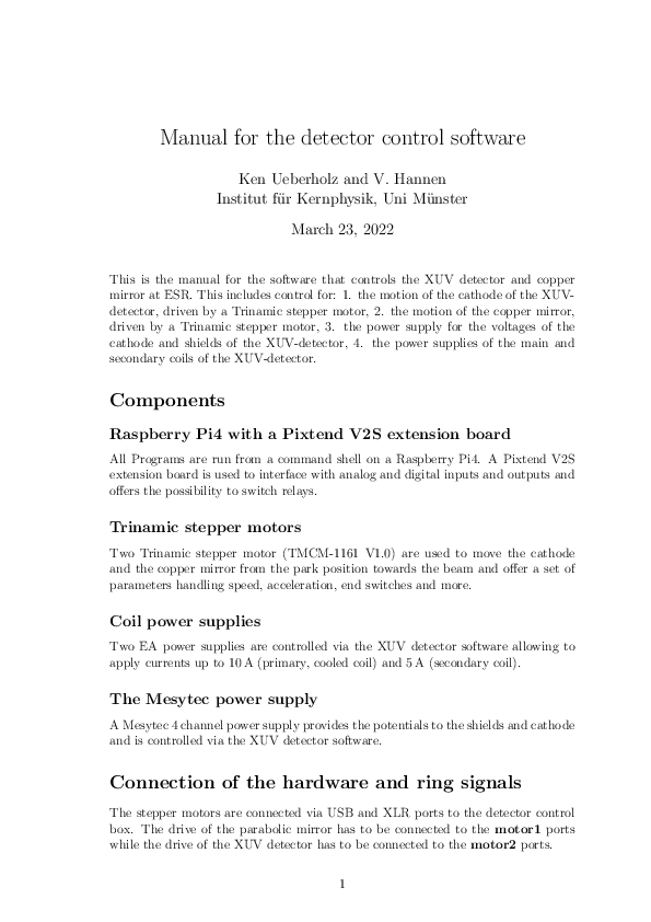
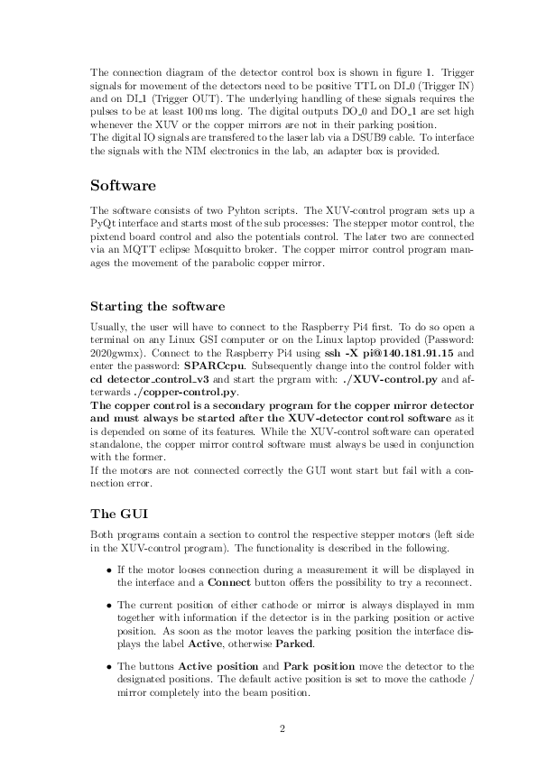
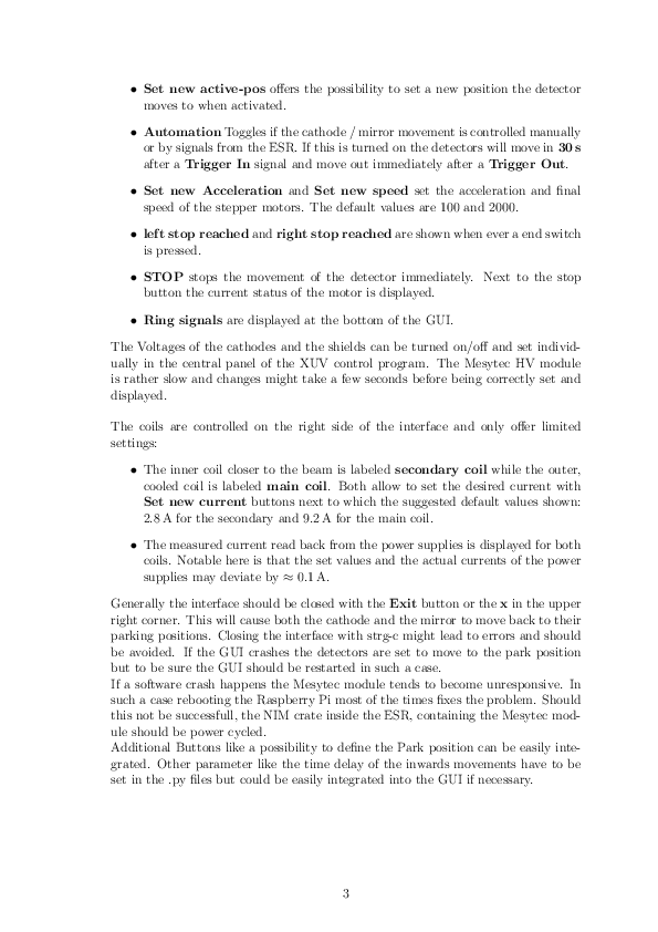
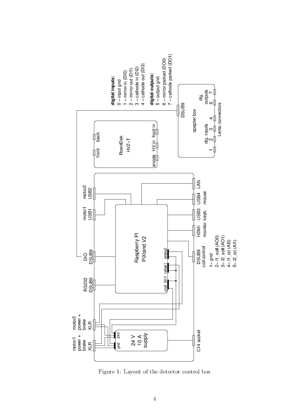
Attached you find a manual for the software used to control the movement of the XUV detector and the copper mirror detector.
The software is also used to set the electrode voltages and coil currents of the XUV detector. |
| Attachment 1: Manual.pdf
|
|
|
29
|
Wed Mar 23 15:38:15 2022 |
Carsten | General | Not all lights in the ESR can be switched off |
| Three of the lights in the ESR cannot be switched off. It seems that these lights are now "emergency lights" (with battery?). We will need to find dark plastik foilor similar to cover those lights during our beam time |
|
28
|
Wed Mar 23 11:20:55 2022 |
Simon | Detectors | PMT operating voltages |
During the testing of the PMTs the following operating voltages were applied:

PMT Cu: -1300V
PMT Nord: -2500V
PMT Mitte: -1800V
PMT Süd: -1800V

Further optimization will be necessary during background measurements. |
|
27
|
Mon Mar 21 21:48:46 2022 |
Jan | DAQ | MesyTec Shaper Control |
The MesyTec Shaper & Constant Fraction (MSCF) is used to process the PMT/det signals for the ADC in the second DAQ.
It can be setup on its front panel, but single channel setup is very tedious.
Remote control of the settings is possible using an epics server and client.

All of the following is done with the "litv-exp" user:

server: atpnuc001 (in the screen session "E142")
client: lxg1275

The server should run undisturbed, but in case of a power failure, you can start the server like this:
> ssh litv-exp@atpnuc001
> cd e142
> ./E142_start_ioc.sh

To check server:
> ssh litv-exp@atpnuc001
> screen -x (CTRL-a CTRL-d to leave screen)

To connect the client gui for remote control, do:
> ssh litv-exp@lxg1275
> E142_epics
The panel is more or less self-explaining.
One thing has to be noted: the Monitor Channel selection is shifted by -1.
I.e., [ch 1] is button [0], etc.

The MSCF settings can be stored and loaded to/from file by using a bash-script.
The settings will be saved/loaded from:
/u/litv-exp/e142/mscf_settings/
files names are "setting_e142.<linux_timestamp>"

The scripts are also in /u/litv-exp/e142/mscf_settings/
use
./mscf_save.sh                   for saving the current settings to a new file
use
./mscf_load_last.sh              to load the last settings file (by timestamp in the filename)
use
./mscf_load_file.sh <filename> to load the settings of a specific file |
|
26
|
Mon Mar 21 17:03:47 2022 |
| DAQ | Changing code of go4 |
Correction: Comments in C/C++ start with // , i.e. forward slash
//--2022-mm-dd HH:MM comment on the respective change.
| Quote: | We agreed to indicate changes in the go4 analysis code according to the
following scheme
\\--2022-mm-dd HH:MM comment on the respective change.
Example:
\\--2022-03-16 16:03 Changed variable N_BUNCHES from 4 to 2
This should allow to find the most recent changes by using the search
function of the applied text editor. |
|
|
25
|
Mon Mar 21 16:33:23 2022 |
| DAQ | Changing code of go4 |
We agreed to indicate changes in the go4 analysis code according to the
following scheme
\\--2022-mm-dd HH:MM comment on the respective change.
Example:
\\--2022-03-16 16:03 Changed variable N_BUNCHES from 4 to 2
This should allow to find the most recent changes by using the search
function of the applied text editor. |
|
24
|
Mon Mar 21 10:46:18 2022 |
Rodolfo | DAQ | TDC & Scaler description channels |
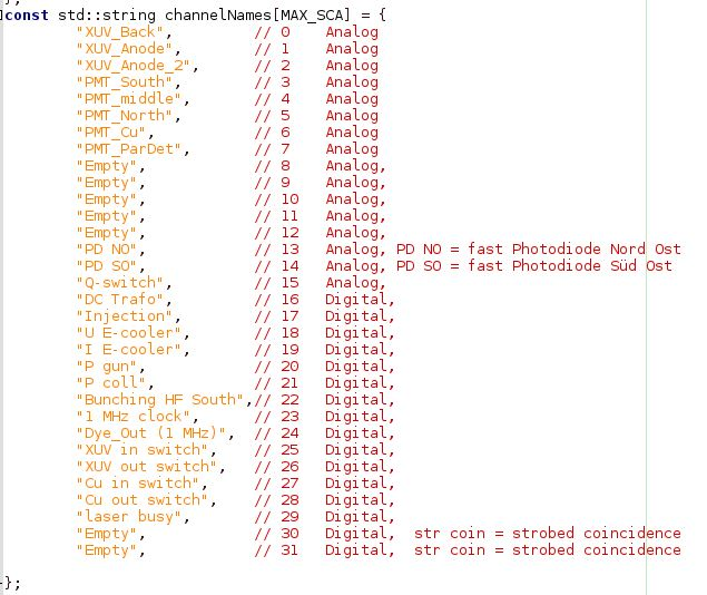
For the First Vuprom we have the following channel configuration (Stand:21.03.2021).
Please note 1.
- CH 0 to CH 15 are the TDC channels
- CH 16 to CH 31 are the SCALER channels
Please note 2.
This is still under construction |
| Attachment 1: Screenshot_TLdaInputDescription_21-03-2022.JPG
|
|
|
23
|
Mon Mar 21 09:18:28 2022 |
Rodolfo | Accelerator | Pressure at North-East Arc |
Our vacuum expert has reply. The "IZ Pump" in this region was off.
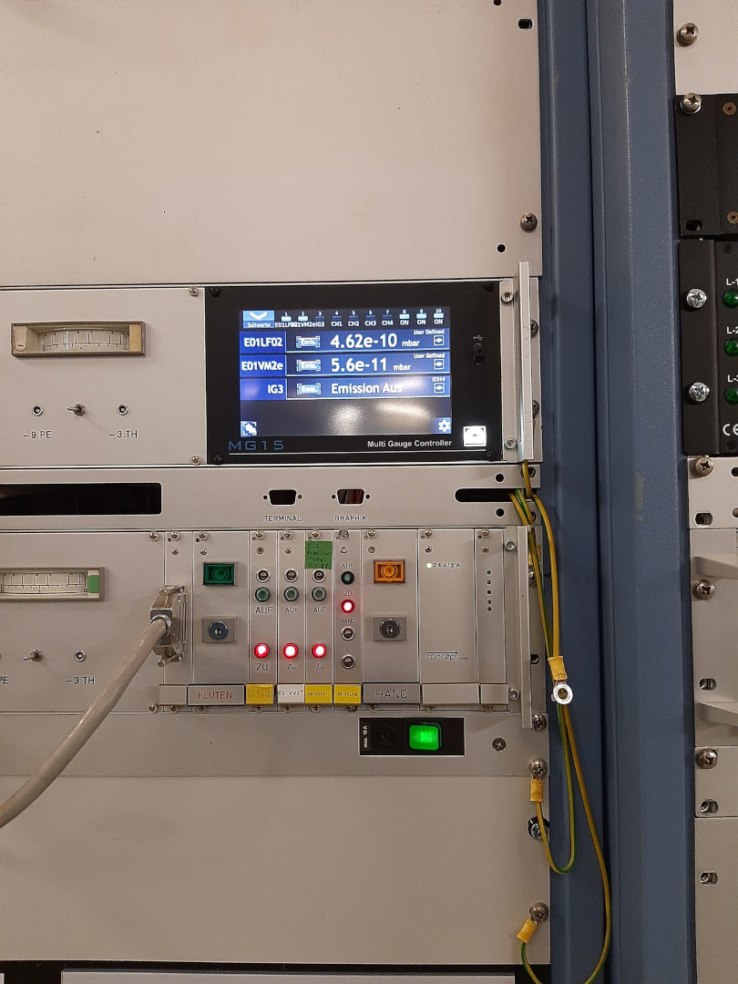
| Quote: | The pressure at the north-east arc of ESR, where the laser window is located, looks suspicious. The sensor E01LF02 shows a value of 7.26E-8 mbar. For comparison I have also upload a photo taken on 07.02.2022 where the pressure was 4.62E-10. We have contacted the vacuum expert and asked for his opinion. Waiting for the reply ...
Bilder: R. Sánchez |
|
|
22
|
Fri Mar 18 16:58:26 2022 |
Rodolfo | Accelerator | Pressure at North-East Arc |
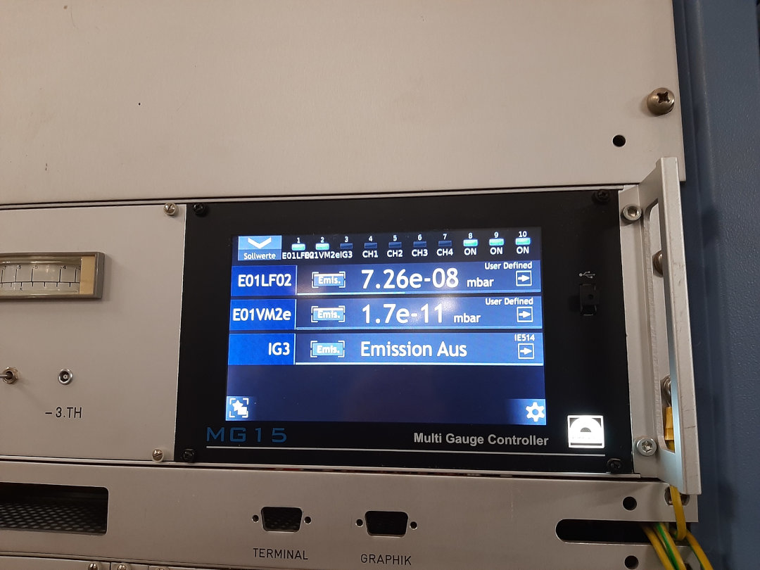
The pressure at the north-east arc of ESR, where the laser window is located, looks suspicious. The sensor E01LF02 shows a value of 7.26E-8 mbar. For comparison I have also upload a photo taken on 07.02.2022 where the pressure was 4.62E-10. We have contacted the vacuum expert and asked for his opinion. Waiting for the reply ...
Bilder: R. Sánchez |
| Attachment 1: Druck_E01LF02_18-03-2022.jpg
|
|
| Attachment 2: Druck_E01LF02_07-02-2022.jpg
|
|
|
21
|
Fri Mar 18 16:51:27 2022 |
Carsten | DAQ | Main DAQ /MBS error |
MBS error "TDC data ready wait" solved. Common stop trigger (20 kHz) was missing. (according to Sebastian) |
|
20
|
Fri Mar 18 09:18:38 2022 |
Rodolfo | Accelerator | Vacuum leak, ODR |
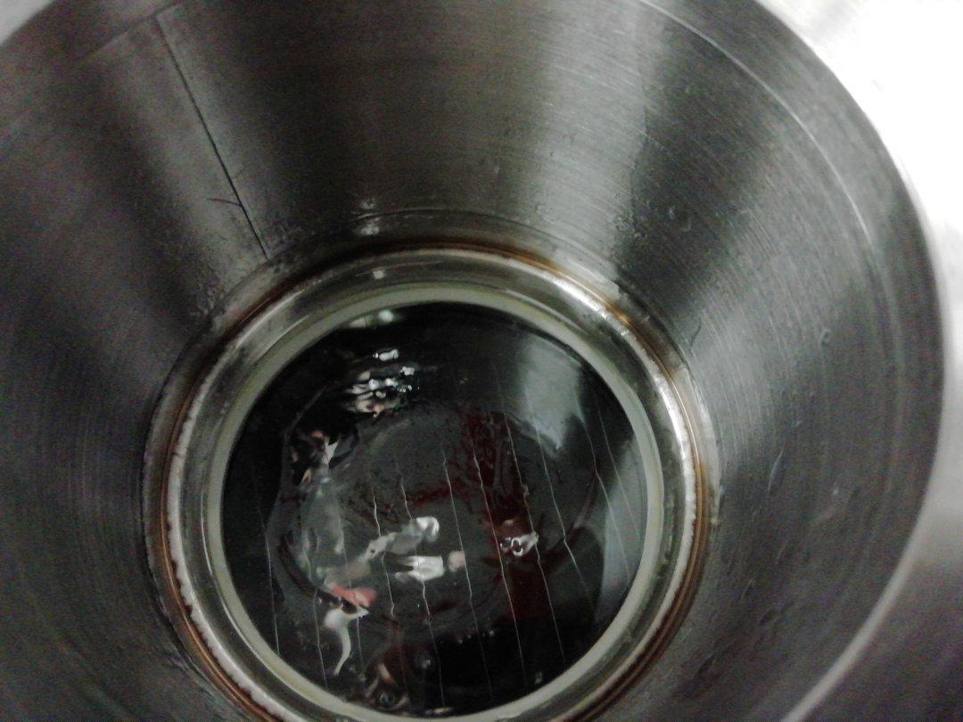
After the beaking out process we got a vacuum leak in one of the MgF2 windows (Referenz: PMT South) of the optical detection region (ODR) Stand 17.03.2022. In order to avoid breaking the vacuum again and a second beaking out process we had to spread vacuum seal on the window.
The window shows now no leaks, Stand 18.03.2022. We are allowed to install a detector on this viewport, as soon as the detector does not have contact with the window (we got the consent of our vacuum expert). Bild: K. König. |
| Attachment 1: MgF2-Window_VACSeal.jpg
|
|
|
19
|
Thu Mar 17 17:56:33 2022 |
Kristian | Calibration | HV dividers |
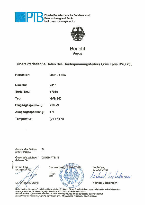
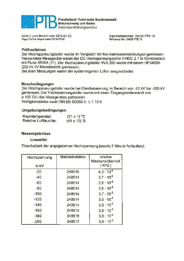
PTB HV dividers arrived. Divider ratios are:

PT120:          12003,341
PT200.1:        19859,033
Ohmlabs: 248517 |
| Attachment 1: Bericht_PTB_verbesserter_Teiler_2018.pdf
|
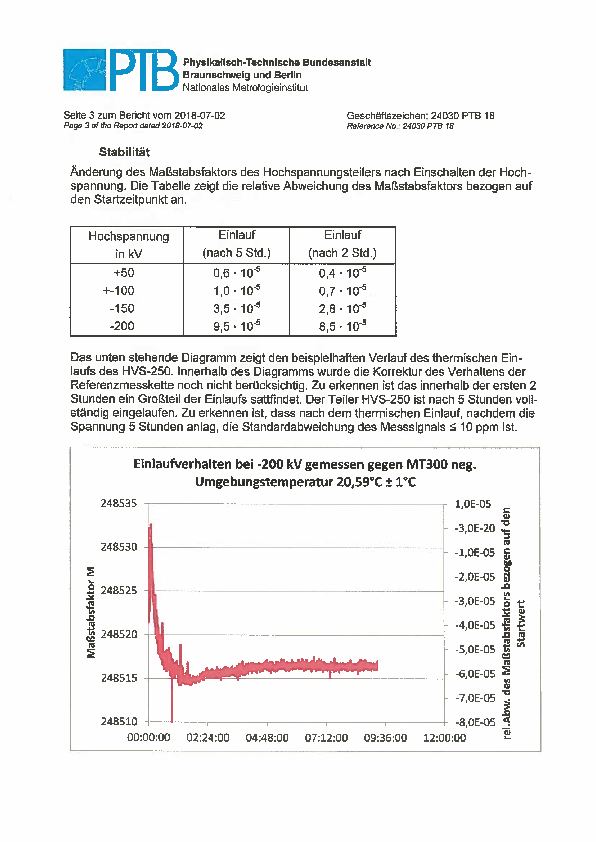
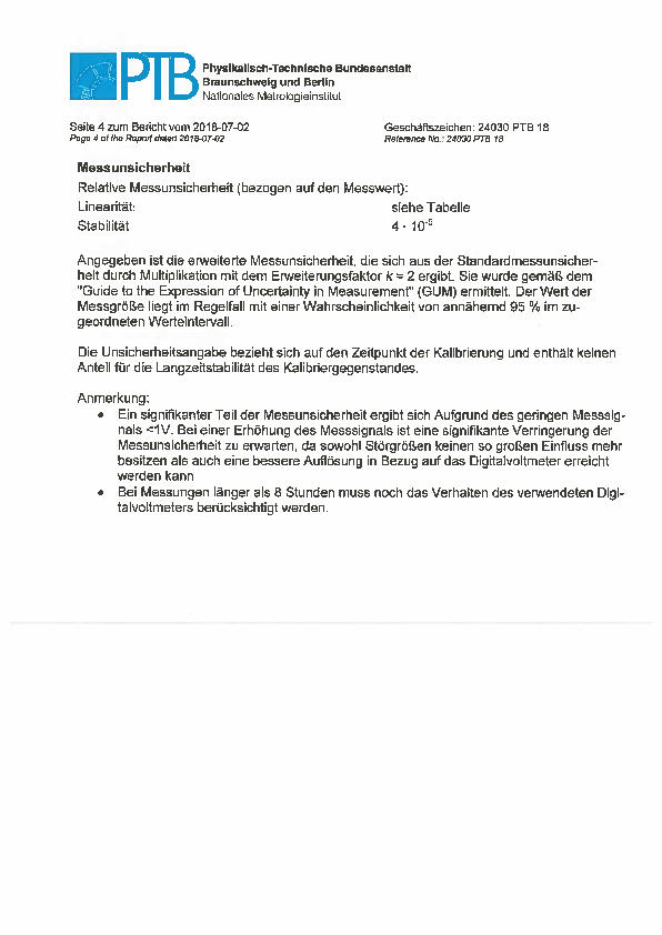
|
|
18
|
Thu Mar 17 17:37:49 2022 |
Rodolfo | Accelerator | High voltage dividers for E-Cooler |
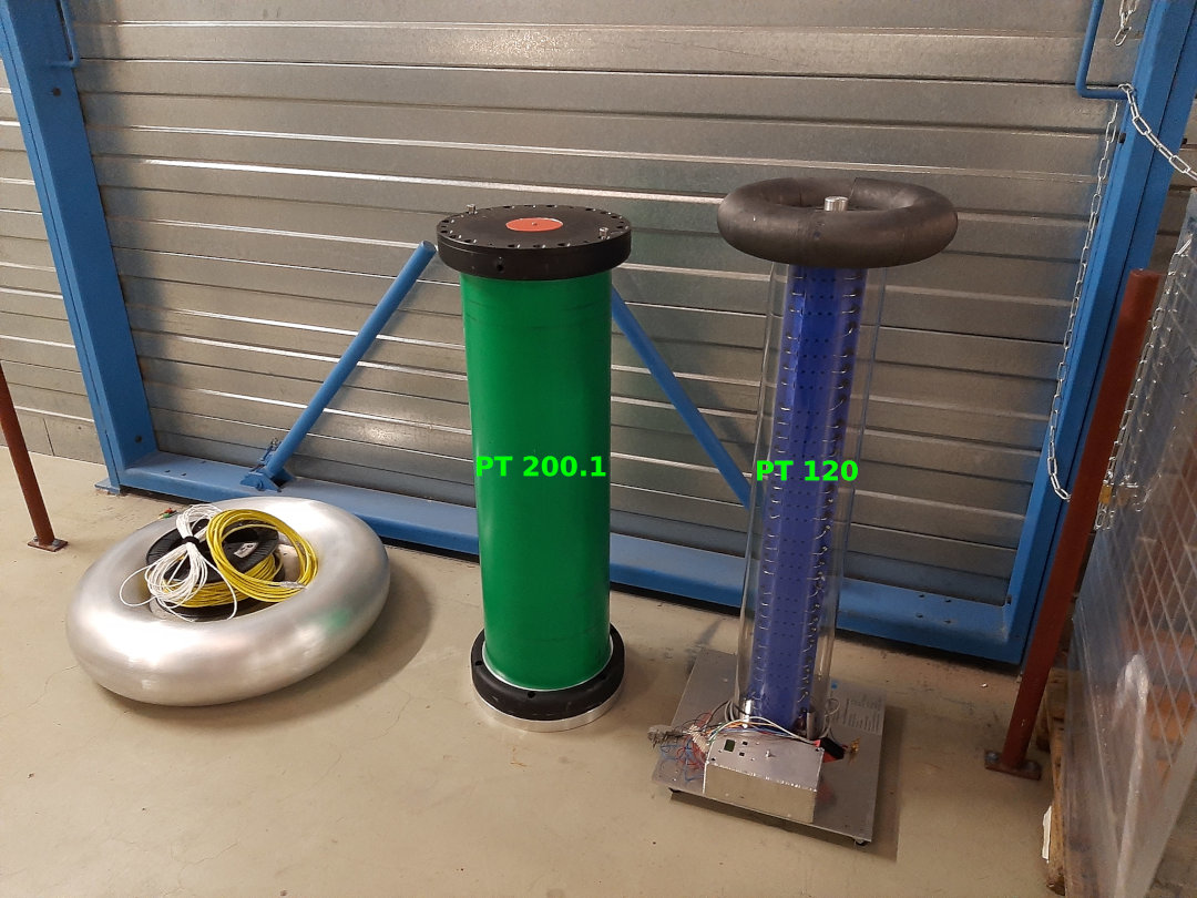
Two dividers, from PTB-Braunschweig, have been deliver today. We will use them to monitor the electron-cooler voltage in situ.
- PT120 (up to -120 kV) with scaling factor: 12003.341, and
- PT200.1 (up to -200 kV) with a scaling factor: 19859,033.
Tomorrow (Friday 18.3.) we will install them in the Faraday cage at ESR.
PT120 will be use for the "Channeling experiment" (E137 Bräuning-Demian) and the PT200.1 for the "Thorium experiment" (E142 Brandau). |
| Attachment 1: PTB_Spannungsteiler_Mar2022.jpg
|
|
|
17
|
Wed Mar 16 12:04:40 2022 |
Kristian | Detectors | HV cable to particle detector South |
Checked HV cable to particle detector south. Label is HV2 Scraper.

Connected to Messplatz III HV5 |
|
16
|
Wed Mar 16 08:31:52 2022 |
Kristian | DAQ | Check cables and timing |
Konstantin and I generated a signal in the Messhütte and sent it to the ESR.
There, we used a 44m BNC cable that was sufficently long to reach all detectors.
Our signal was connected instead of the PMT/PD. Hence, it was a roundtrip measurement.
In the Messhütte we checked the delay between the generated signal.

PD North 1460(1)ns
PD South 1455(1)ns
Particle North 1239(1)ns
Particle South 1179(1)ns
UV North 1322(1)ns
UV Middle 1322(1)ns
UV South 1321(1)ns
Cu 1322(1)ns

We also checked the time delay of our cable to the detectors by measuring the reflection of the unterminated cable.
Function generator to detector: 1520(5)/2 ns
Function generator to scope: 5.1(5) ns
Total: 765(3) ns |
|
15
|
Thu Mar 10 15:20:26 2022 |
Jan | DAQ | analog branch signal patches to Messhütte |
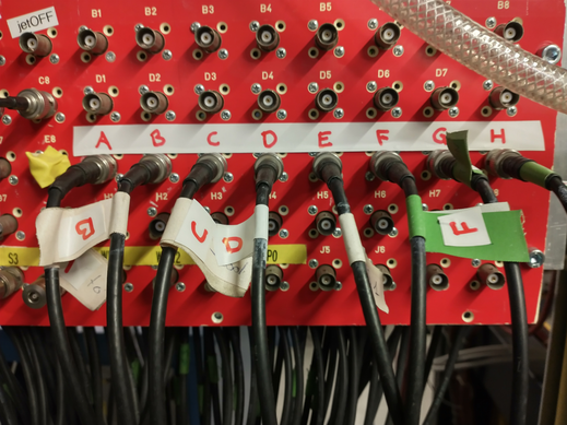
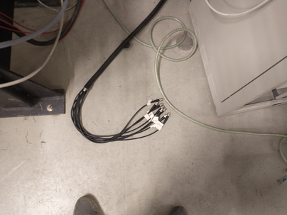
The additional signals from PMTs and XUV detector needed for spectroscopic analysis in the second DAQ are patched to AP Messhütte (MH) via the red patch panel at the inside of the target region. The patch channels F1 to F8 (also labeled A to H in red on white) are used and extended by a cable bundle to reach below the mirror chamber. Inside the MH the signals arrive at the red patch panel and are forwarded to the blue patch panel close to the laser DAQ using channels 1 to 8 (also labeled A to H).

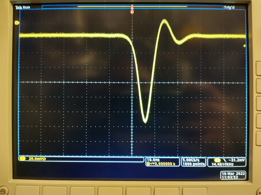
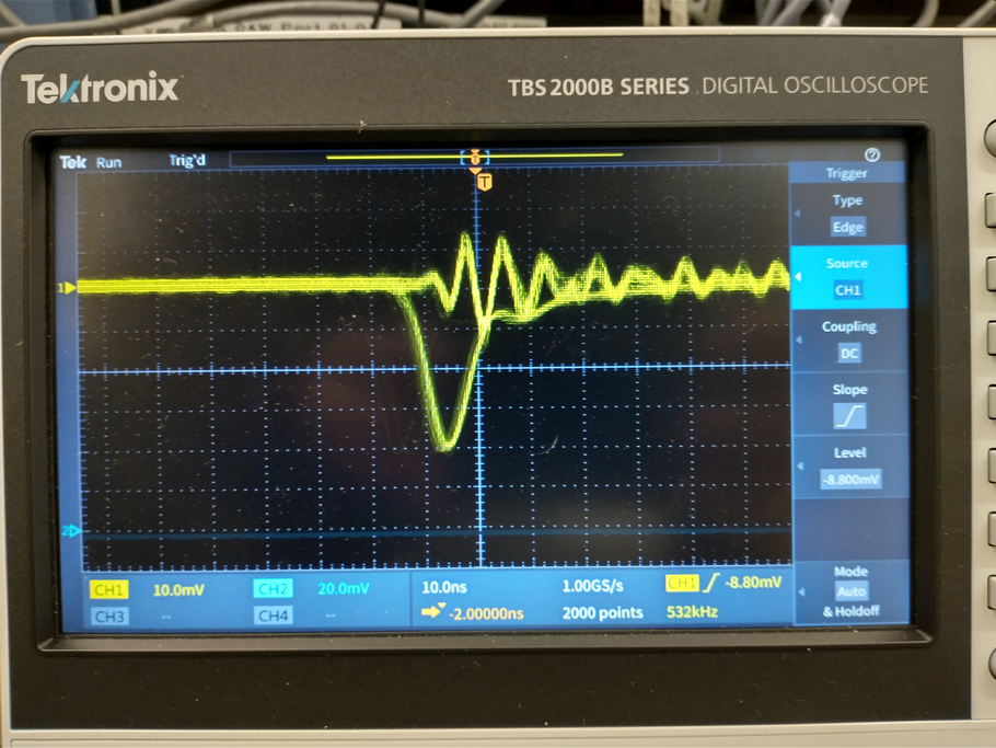
The entire connection for these 8 channels from the mirror chamber to the blue panel has been tested with a pulser signal of ~115mV amplitude. After transfer the amplitude has decreased to ~40mV, see also attached fotos.

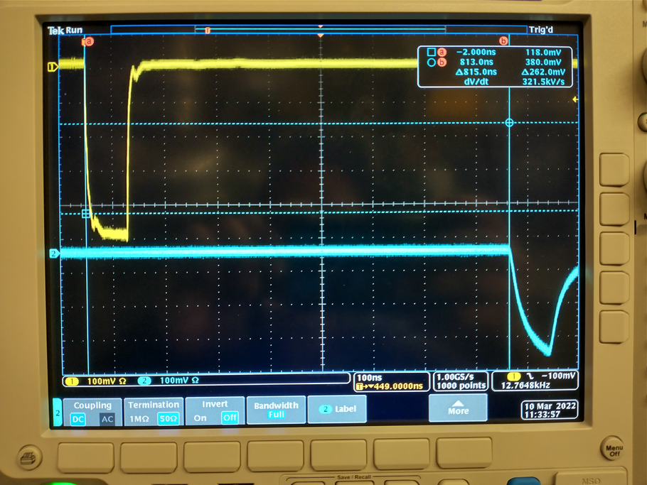
The signal transport time from the mirror chamber to the blue panel is ~407 ns. This was measured by patching a logic puls from ESR to MH and back to ESR, as show in the delay_ESR... foto attached. |
| Attachment 1: red_panel_ESR.jpg
|
|
| Attachment 2: pulser_signal_ESR.jpg
|
|
| Attachment 3: pulser_signal_MH.jpg
|
|
| Attachment 4: delay_ESR-MH-ESR.jpg
|
|
| Attachment 5: cable_bundle_mirror_chamber.jpg
|
|
|
14
|
Thu Mar 3 21:39:21 2022 |
Rodolfo | Laser | Dye solution, DCM in Ethanol and DMSO |
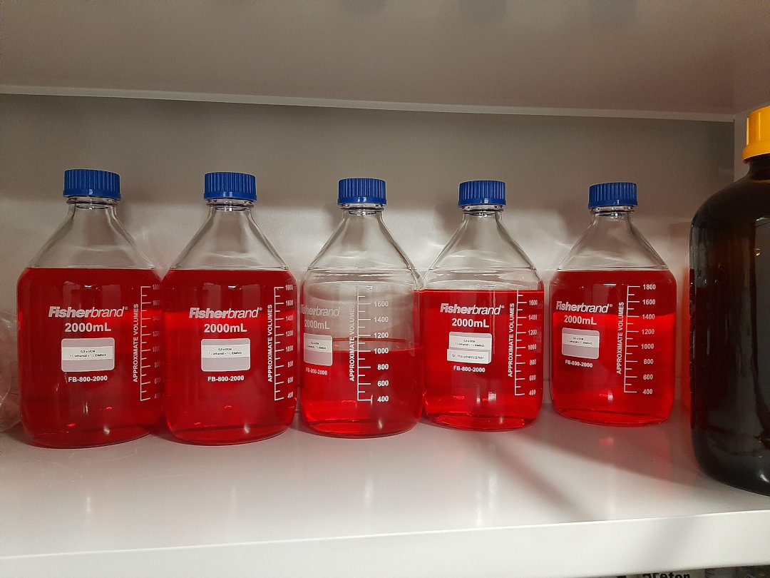
I have prepared a new dye solution of DCM in Ethanol and DMSO (1:1). The concentration of the "oscillator + preamplifier" is 0,3 g/l. The concentration of the "main amplifier" is 0,0375 g/l or "1/8" the concentration of the "oscillator".
Using 500 mJ pump energy (@ 532 nm) I get 120 mJ ouf of the dye laser (@ 640 nm). After the Frequency Conversion Unit I get 32 mJ (@ 320 nm).
Because the Biochemielabor will be not accessible during the first days of the Thorium beamtime, I have prepared enough reservoir for 7 days (assuming the laser system will run 24/7). |
| Attachment 1: FarbstoffVorrat_Thorium.jpg
|
|