| ID |
Date |
Author |
Category |
Subject |
|
28
|
Wed Mar 23 11:20:55 2022 |
Simon | Detectors | PMT operating voltages |
During the testing of the PMTs the following operating voltages were applied:

PMT Cu: -1300V
PMT Nord: -2500V
PMT Mitte: -1800V
PMT Süd: -1800V

Further optimization will be necessary during background measurements. |
|
30
|
Wed Mar 23 16:16:42 2022 |
V. Hannen | Detectors | Control software for XUV and copper mirror detector |
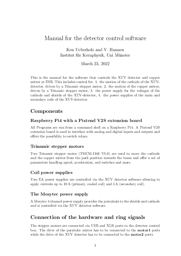
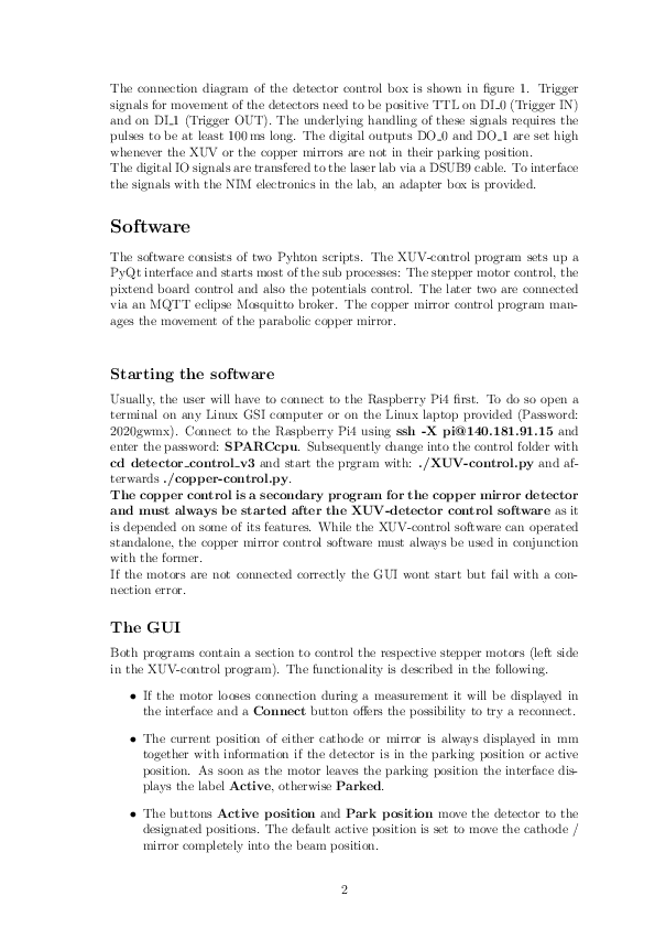
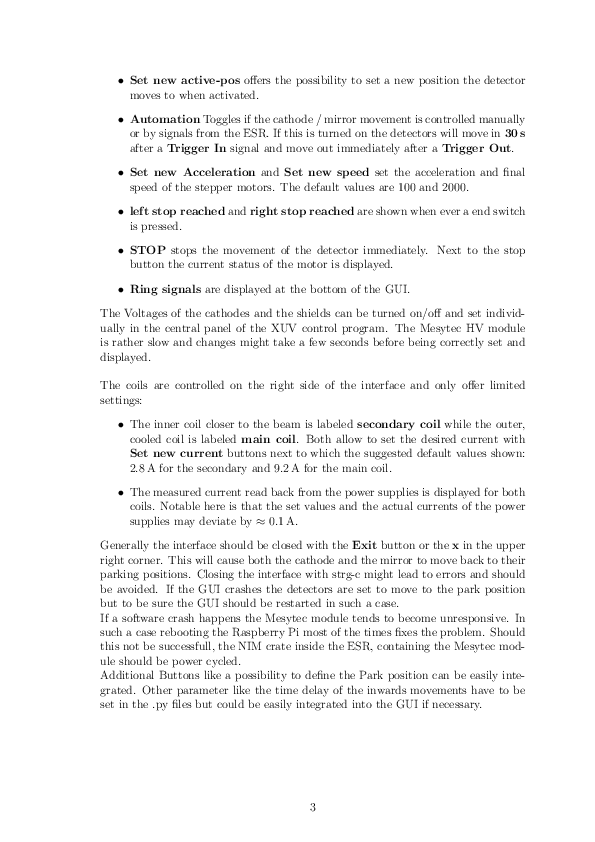
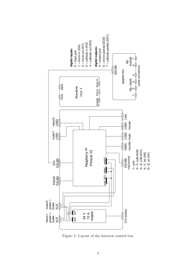
Attached you find a manual for the software used to control the movement of the XUV detector and the copper mirror detector.
The software is also used to set the electrode voltages and coil currents of the XUV detector. |
| Attachment 1: Manual.pdf
|
|
|
31
|
Wed Mar 23 16:58:33 2022 |
V. Hannen | Detectors | Status copper mirror and XUV detectors |
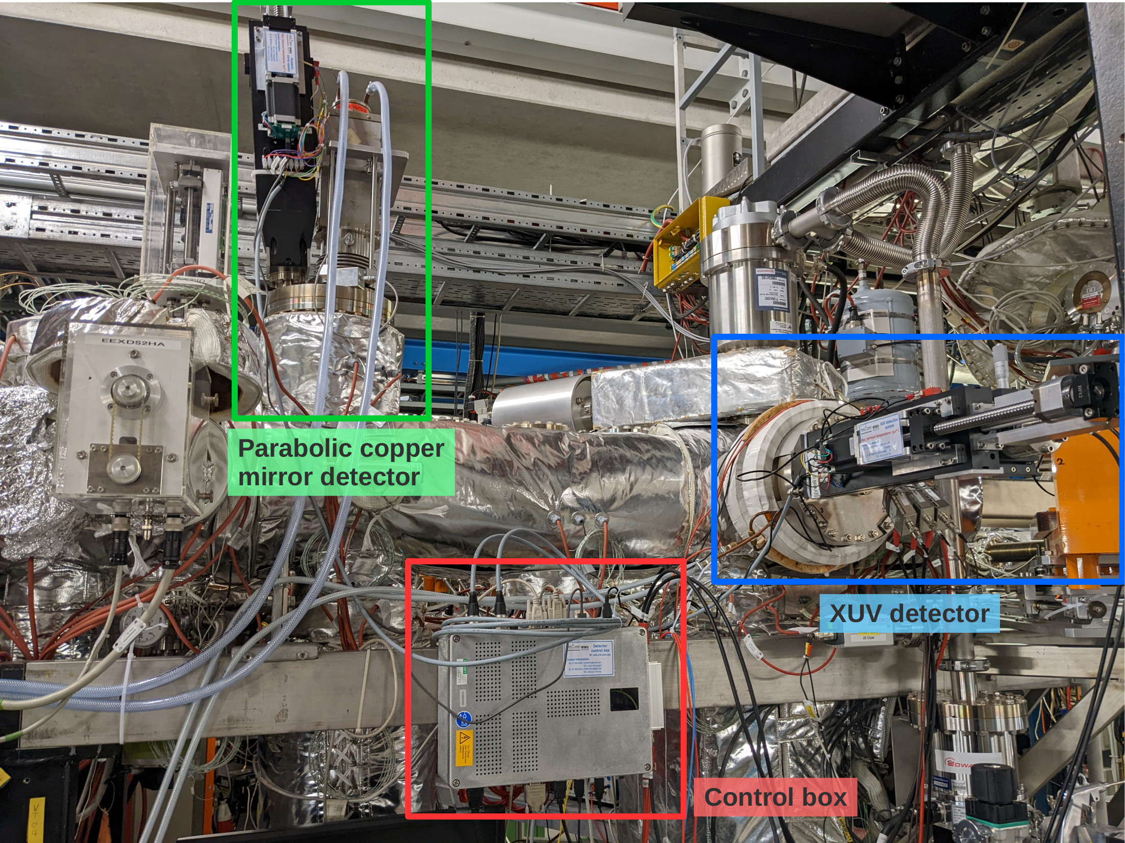
Over the past days, the parabolic copper mirror and XUV detectors haven been prepared and tested for the upcoming beamtime (see first attached photo for an overview of the detectors).
The positioning of the mirror and the cathode of the two detectors in their central positions in the beampipe have been adjusted. To reach this central position, the XUV cathode has to be moved 147 mm out of the parking position, while the parabolic mirror has to be moved by 173 mm. While the parabolic mirror will most probably always be driven the full pathlength to make maximum use of the Doppler shift of the emitted photons, the cathode will be placed somewhere in between parking and beam position to minimize background while still having a good detection efficiency.
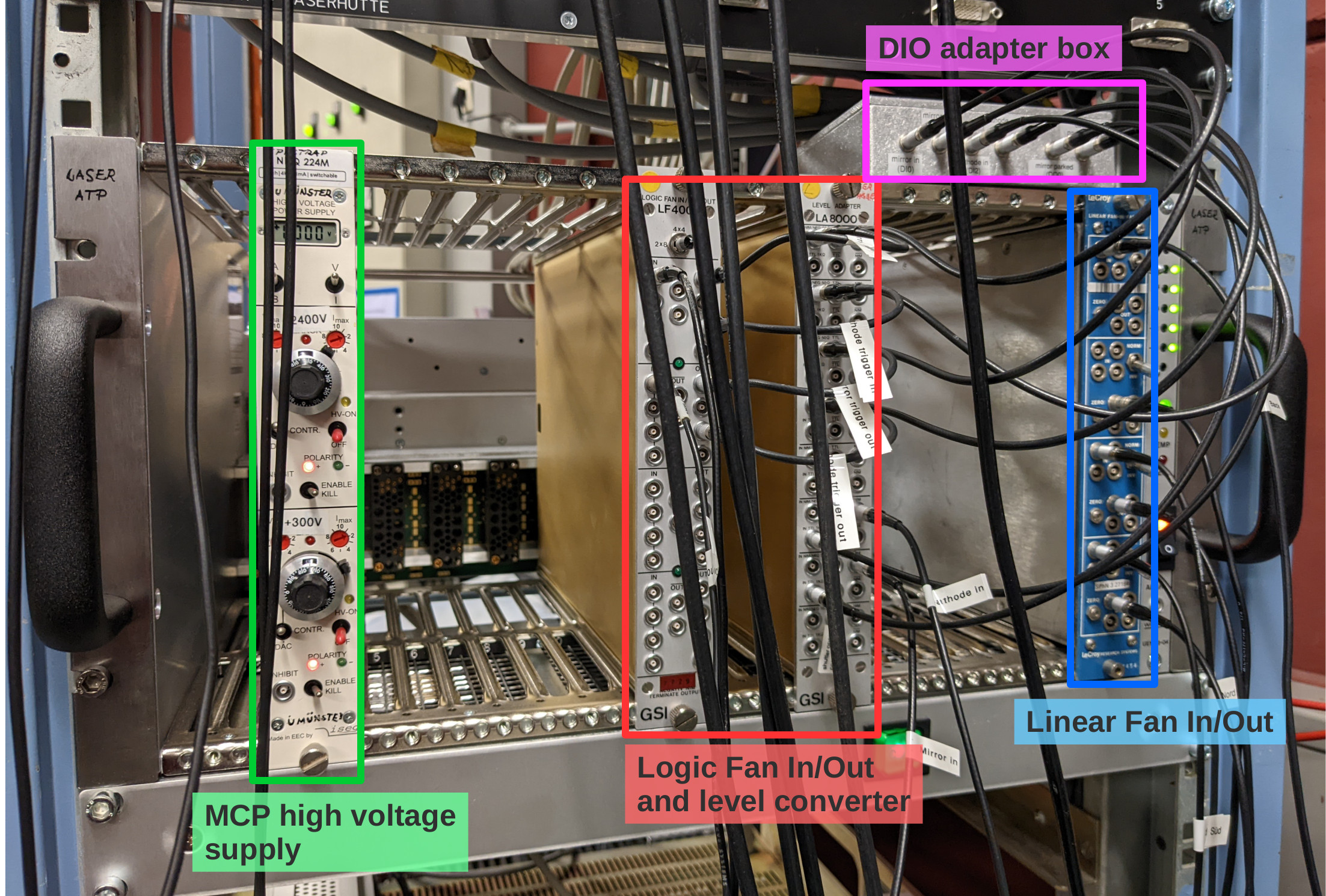
The MCP of the XUV detector is supplied with high voltage using an iseg 2 channel HV supply located in a NIM crate in the laser lab (see second photo). The required voltages are: +2400 V for the anode (upper channel) and +300 V for the MCP front (bottom channel).
The PMT of the copper mirror detector is supplied with HV by the same module as the PMTs on the new mirror chamber and has to be operated at a voltage of -1300 V.
The analog signals of both detectors are amplified by a factor 100 inside the ESR and patched through to the "Messhütte". For the MCP, the anode and MCP back signals are used (the MCP front signal is weak and noisy and doesn't give additional information). The MCP back signal has a positive polarity and is inverted in a linear Fan In/Out module in the NIM crate in the laser lab prior to discrimination.
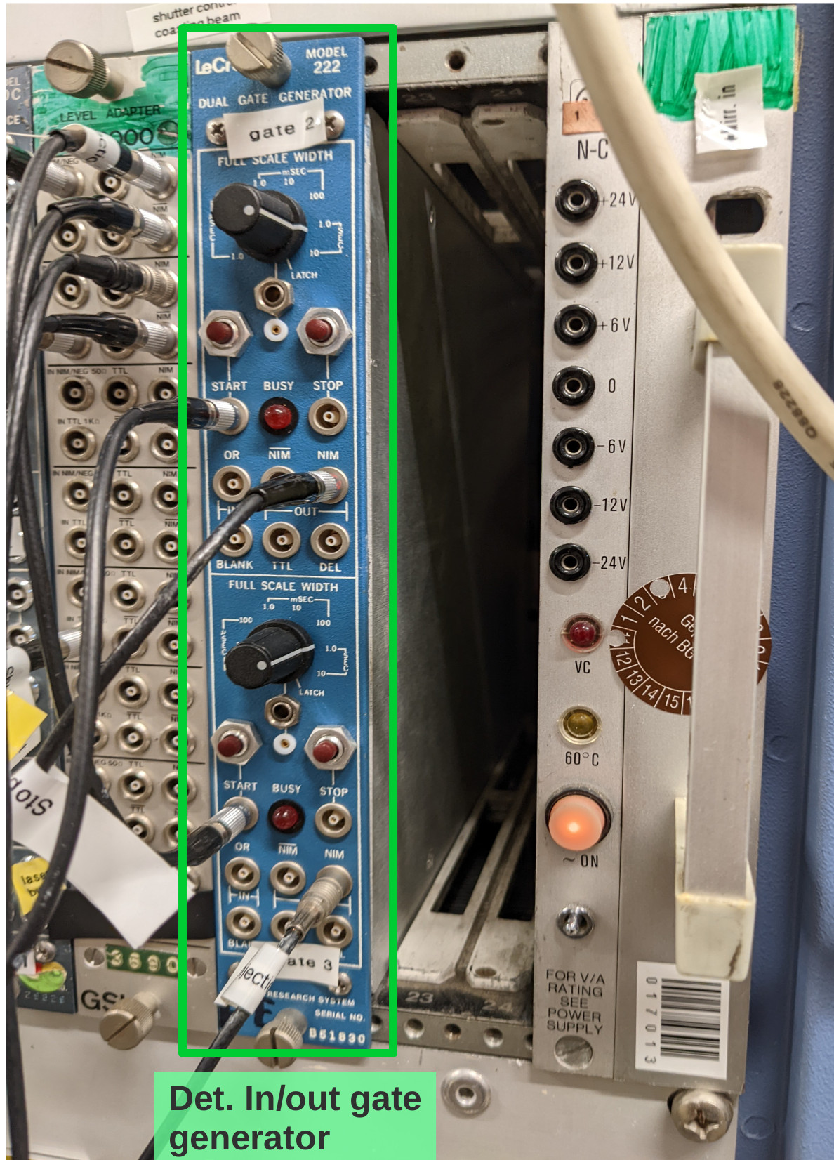
To trigger the movement of the copper mirror and the cathode from their respective parking positions to the measuring positions and back during each filling cycle of the ESR, two signals labeled "trigger in" and "trigger out" need to be provided from the ESR. These signals have to be connected to the "START" inputs of the gate generator in the Messhütte shown in the third photo. The upper channel processes the "trigger out" signal, the lower channel the "trigger in" signal. From the gate generator the signals are patched to the laser lab, where they are multiplied and converted to TTL in the NIM crate shown in photo 2, and transfered to the detector control box using the adapter on top of the crate. Automatically moving the detectors in and out only works when the control software is running and the "Automation" radio buttons are checked (see software manual in Elog entry 30).
Still to be done:
- connecting the analog signals to CFDs in the Messhütte and subsequently to the TDC inputs
- determining dark count rates when all pressure gauges in the straight section on the detector side of the ESR are switched off
- check influence of new ion getter pump on the XUV detector dark count rate.
Should we not be around and help is needed with these detectors call:
Volker Hannen - 0176 50129187
Ken Ueberholz - 01578 5999489 |
| Attachment 1: det-overview.jpg
|
|
| Attachment 2: laserlab-crate.jpg
|
|
| Attachment 3: trigger-module.jpg
|
|
|
40
|
Thu Mar 31 11:49:54 2022 |
Konstantin | Detectors | HV-Supply of particle detectors |
| We cross-checked the cabeling of the particle detectors north and south. Particle detector south is connected to channel HV5 at the yellow "ESR Messplatz III" patch-panel. Particle detector north is connected to channel K5 at the green "ESR Messplatz II" patch-panel. Red high voltage power-supply is used to control the voltage. |
|
42
|
Thu Mar 31 15:53:50 2022 |
Konstantin | Detectors | Control software for XUV and copper mirror detector |
> Attached you find a manual for the software used to control the movement of the XUV detector and the copper mirror detector.
> The software is also used to set the electrode voltages and coil currents of the XUV detector.

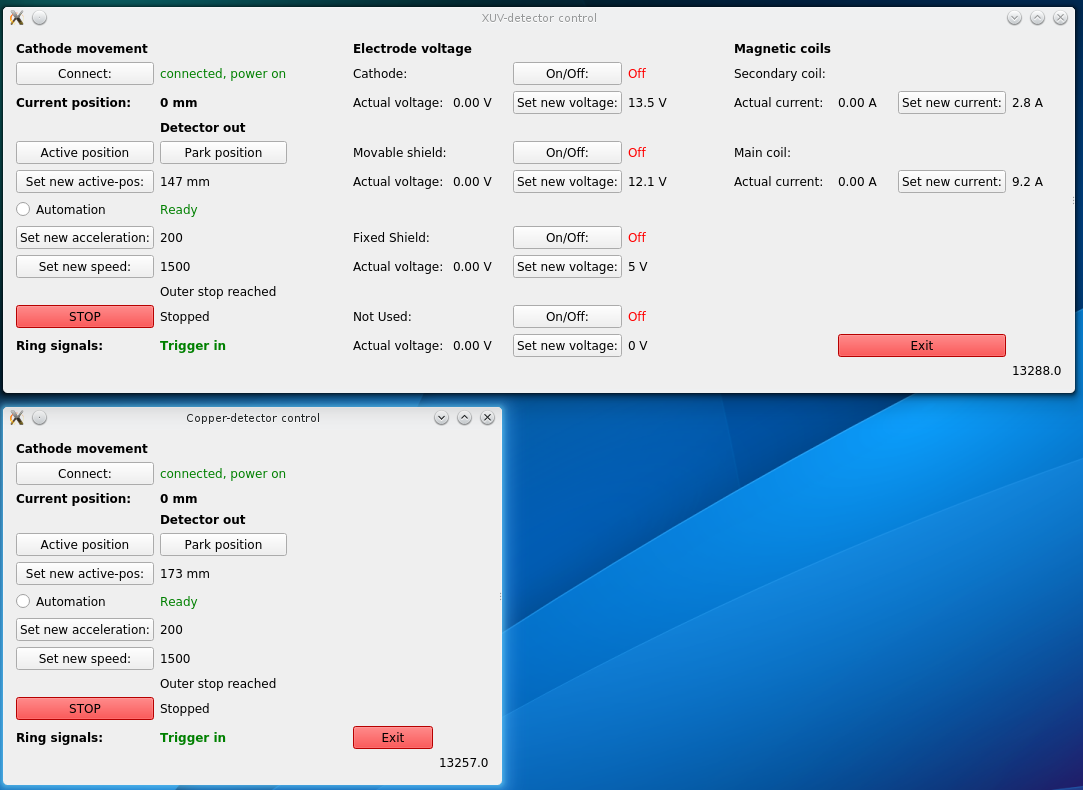
We tested the remote access to the raspberry pi as explained in the manual attached to the original entry of Volker. It was tested from
the linux machine LXG1050. Attached you can find a screenshot of the running program. |
| Attachment 1: XUV_Cu_GUI.png
|
|
|
53
|
Fri Apr 1 15:27:00 2022 |
Rodolfo | Detectors | Nitrogen for UV-PMTs |
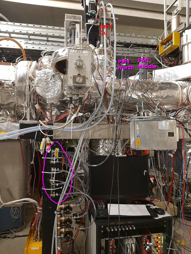
There was a question concerning the nitrogen we use to rinse the "Solar Blind PMTs".
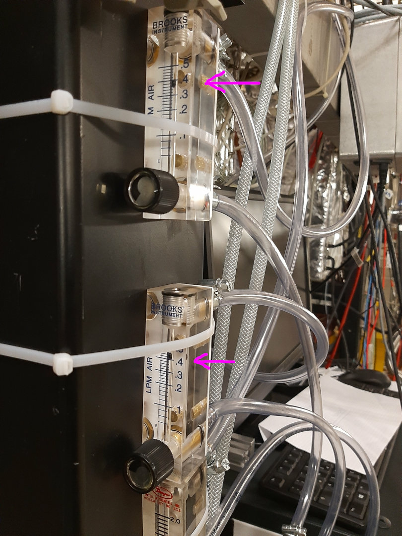
- I have checked the nitrogen flow rate this afternoon (14:00) and it was a level of 0.2 LPM.
- I have increased this now to 0.4 LPM.
In the pictures below you can see where the "fine tunning" valves are located.
Bilder: R. Sánchez |
| Attachment 1: Stickstoff_f_PMTs.jpg
|
|
| Attachment 2: Stickstoff_Flussrate.jpg
|
|
|
54
|
Fri Apr 1 15:52:23 2022 |
Rodolfo | Detectors | UV PMT South |
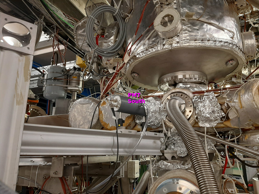
The "Solar Blind PMT" labeled as "PMT South" has been installed by Simon and Max in the gas target chamber on a CaF Viewport. The PMT is pointing directly to the center chamber.
- I have covered the support of the PMT and the flange with additional aluminum foil in order to try to reduce the straight light.
- I will check the signal of the PMT as soon as the lighting inside the cave will be turned off.
Bild: R. Sánchez |
| Attachment 1: PMT_Sued_Target.jpg
|
|
|
55
|
Fri Apr 1 16:46:33 2022 |
Carsten | Detectors | All pressuzied air drives are tested now and are working properly |
All pressuzied air drives are tested now and are working properly |
|
57
|
Fri Apr 1 18:30:38 2022 |
Carsten | Detectors | Positions / Voltages threshlds for particle detectors |
DC beam 238U92+ (205kV, e-beam)
We used the detector NA_SZ to determine the central primary-beam (238U92+) position by observing the Schottky-signal while moving the detector inside.
The beam position is 43 mm (wehre the beam is almost gone").
NA_SZ
In the pocket of the NA_SZ we mounted the thick "old pilot U" scintilator since the original one foreseen is defect, see other post.
CFD Model CAEN N853
800V position 20mm pulse height 1V
750V position 10mm pulse height 0.82V, CFD, Ch7, 247, (247mV according to manual)
SA_SZ
Check positions and voltages of the detector behind the cooler
Yesterday the setting of the scope was x10, so the values written in that post were wrong.
At present we position -20, 1400V, pulseheight 1C, CFD, Ch6, 250 (250mV according to manual)
Scraping from the inside with NI_SZ touches the primary ion beam at 28 and destroys the beam at 27 mm. Thus, the beam presently is on a very inner orbit. |
|
58
|
Fri Apr 1 22:01:14 2022 |
Konstantin | Detectors | PMT operating voltages |
> During the testing of the PMTs the following operating voltages were applied:
>
> PMT Cu: -1300V
> PMT Nord: -2500V
> PMT Mitte: -1800V
> PMT Süd: -1800V
>
> Further optimization will be necessary during background measurements.
Currently, PMT Süd shows a strange behavior resulting in after-pulses up to 1µs. Therefore, the high-voltage was reduced to -1500 V.
However, the after-pulses remain. This should be investigated in more detail at some other point. |
|
59
|
Fri Apr 1 23:12:37 2022 |
Patrick | Detectors | Scraper positions "only primary beam" |
Scraper positions where there is only primary beam for detector tests. Use only one outer and one inner scraper at the same time.
Move detectors out before new beam!
outer:
GE02DD2_G: 0mm
GE01DD2AG: -10mm
inner:
GE01DD2IG: 40mm |
|
60
|
Fri Apr 1 23:47:45 2022 |
Carsten | Detectors | PMT thresholds / PMT north does not allow voltage abow ~ -1kV |
Checked thresholds of PMT with beam and without beam.
The PMT "south" which is now at the gas-jet target has burst-like pulses with a train of many short pulses of duration of about 1us. The signals are taken out of the ADC of the 2nd DAQ (but are still in the VUPROM TDC).
The PMT "middle" (broad-band VUV) has a quite high count rate of about 4-kHz at a few 10e7;; ions in the ring. The rate is very low without ions in the ring but it does not fully scale to low intensities.
At low intensities of a few 10e5;; we still have more than 100 Hz.
For a PMT voltage of -1800V a threshold of 20mV was set which is ok an d we leave it
Note: We see a noise beat of 6ns and 55ns with amplitude of about 15mV to 20mV. The high frequency disappears if we use a battery scope.
PMT "north" small-band VUV
We tried to put the voltage to the wanted level of -2500V. It was not possible to set a voltage higher than about -1000V. WIth this voltage the PMT draw a current of about 200uA and at a voltage above this value it dropped to zero and switched off.
We need to have a closer look at the PMT in the ESR tomorrow with some specialist knowledge. |
|
77
|
Sun Apr 3 11:40:48 2022 |
Shahab, Yuri | Detectors | 245 MHz Resonator tuned to new frequency |
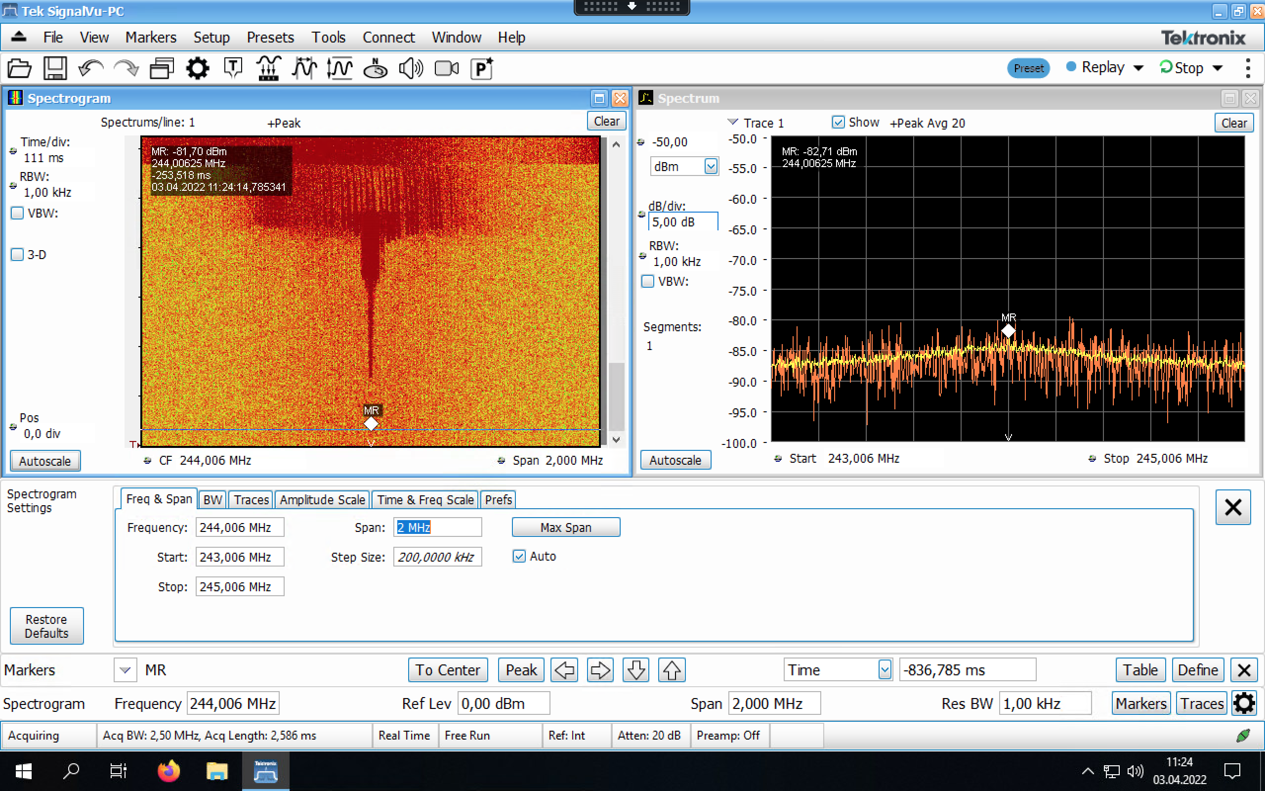
resonance frequency changed from 243.2 MHz to 244.692 MHz by reducing the value of both of the plungers from 395 to 325. Now after movement, the peak is on the resonance. |
| Attachment 1: Screenshot_2022-04-03_at_11.24.15.png
|
|
|
97
|
Tue Apr 5 13:24:40 2022 |
Kristian | Detectors | PMT Cu |
HV cable was in wrong channel in power supply. Now it is back to the correct position. Checked connection at the PMT. |
|
115
|
Wed Apr 6 19:39:08 2022 |
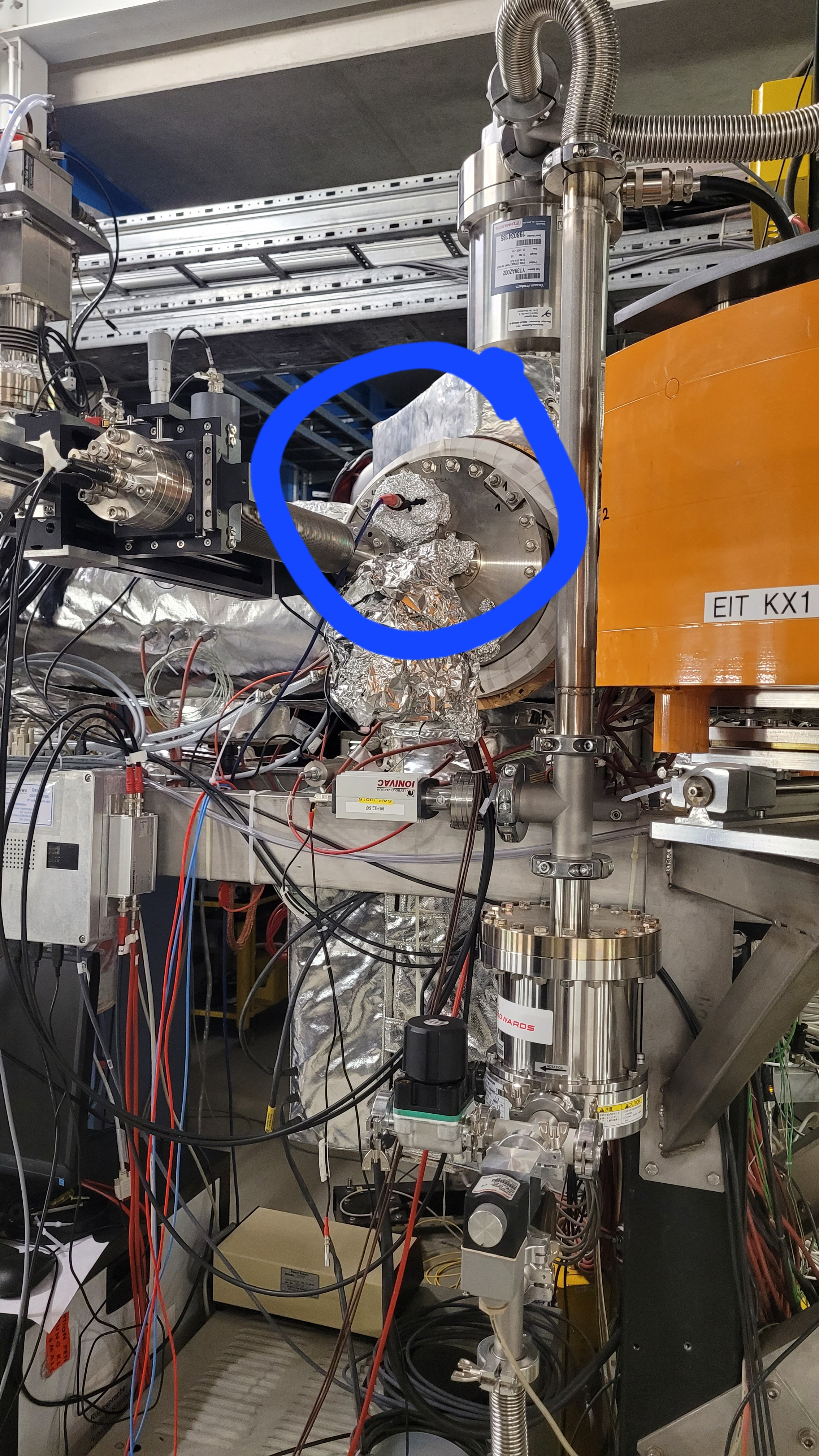
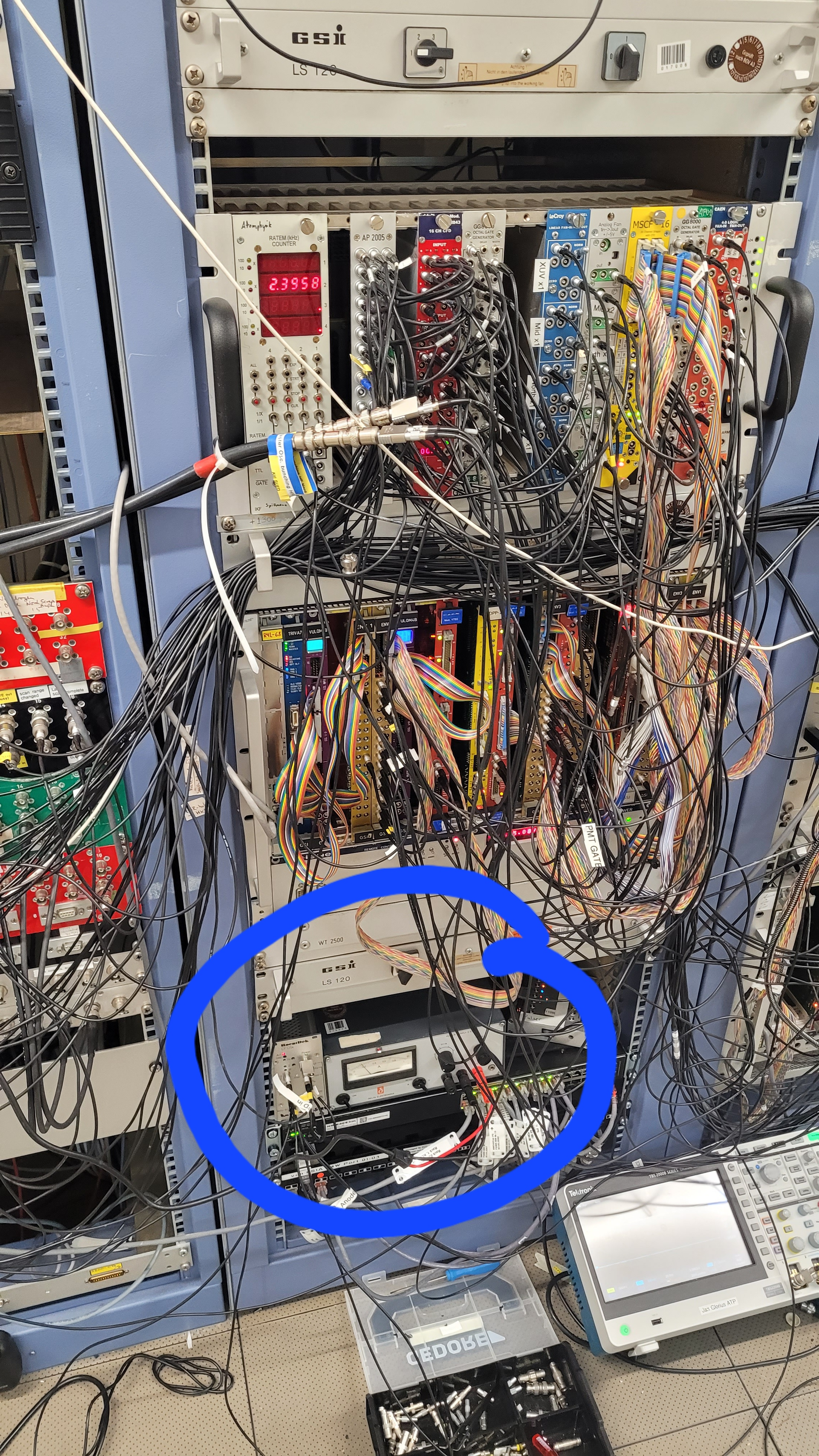
Ken Ueberholz | Detectors | LED installed |
The UV-LED of Münster was connected over
channel 8 to the Messhütte. 6V are
supplied by the power supply (picture 2).
The Led is located at the xuv detector
(picture 1). |
| Attachment 1: 20220406_193541.jpg
|
|
| Attachment 2: 20220406_193439.jpg
|
|
|
116
|
Wed Apr 6 21:03:25 2022 |
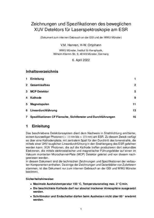
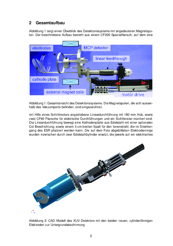
Ken Ueberholz | Detectors | Xuv-Detektor, further information |
Some further information regarding the
xuv-detector and its components. |
| Attachment 1: xuv_detektor.pdf
|

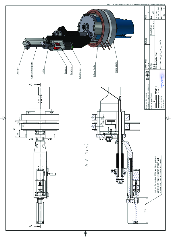
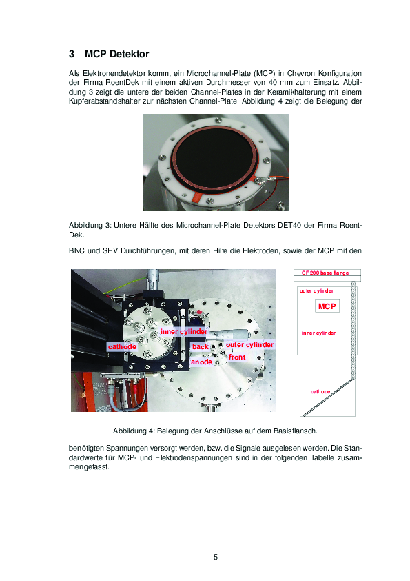

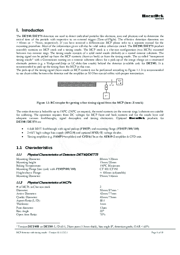
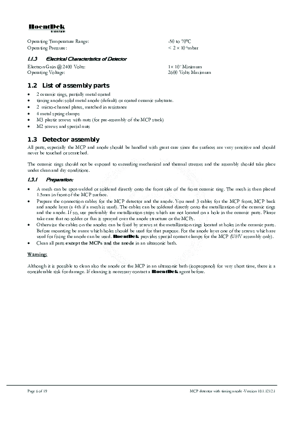
|
|
129
|
Thu Apr 7 05:55:17 2022 |
Ken Ueberholz | Detectors | XUV-Detector Mesytec crash |
When the XUV-detector has to shut down unexpectedly, it can happen that the Mesytek power supply crashes and can't be
communicated with. If this happens the Mesytec PS needs to be restarted from hand inside of the ESR. This can be done by
restarting the crate located at the bottom of the XUV-detector.

This crash happened during the night shift today and the Mesytec should be restarted today as soon as possible. For
example when the laser stabilization gets fixed.

In normal operation this should never happen if no mistakes are made. |
|
137
|
Thu Apr 7 14:01:22 2022 |
Sebastian, Max | Detectors | Mesytec reset |
The Mesytec crate was turned off and on again.

It is again possible to communicate with the XUV detector via python to apply voltage and current. |
|
139
|
Thu Apr 7 14:13:27 2022 |
Danyal | Detectors | new PMT south |
I have replaced the PMT south (looks at the gas target).
in the hope that this will produce less dark counts.
Thus far, the dark countrate is low (few Hz).

brand: ET enterprises
type:  2" photomultiplier, 9423B
High voltage: -2.45 kV  (up to -3.5 kV)
spectral range: 110 - 230 nm

The power comes from an additional 2.5 kV supply.
(I have changed the cable: was CH0 before) |
|
141
|
Thu Apr 7 16:45:10 2022 |
| Detectors | Detector distances |
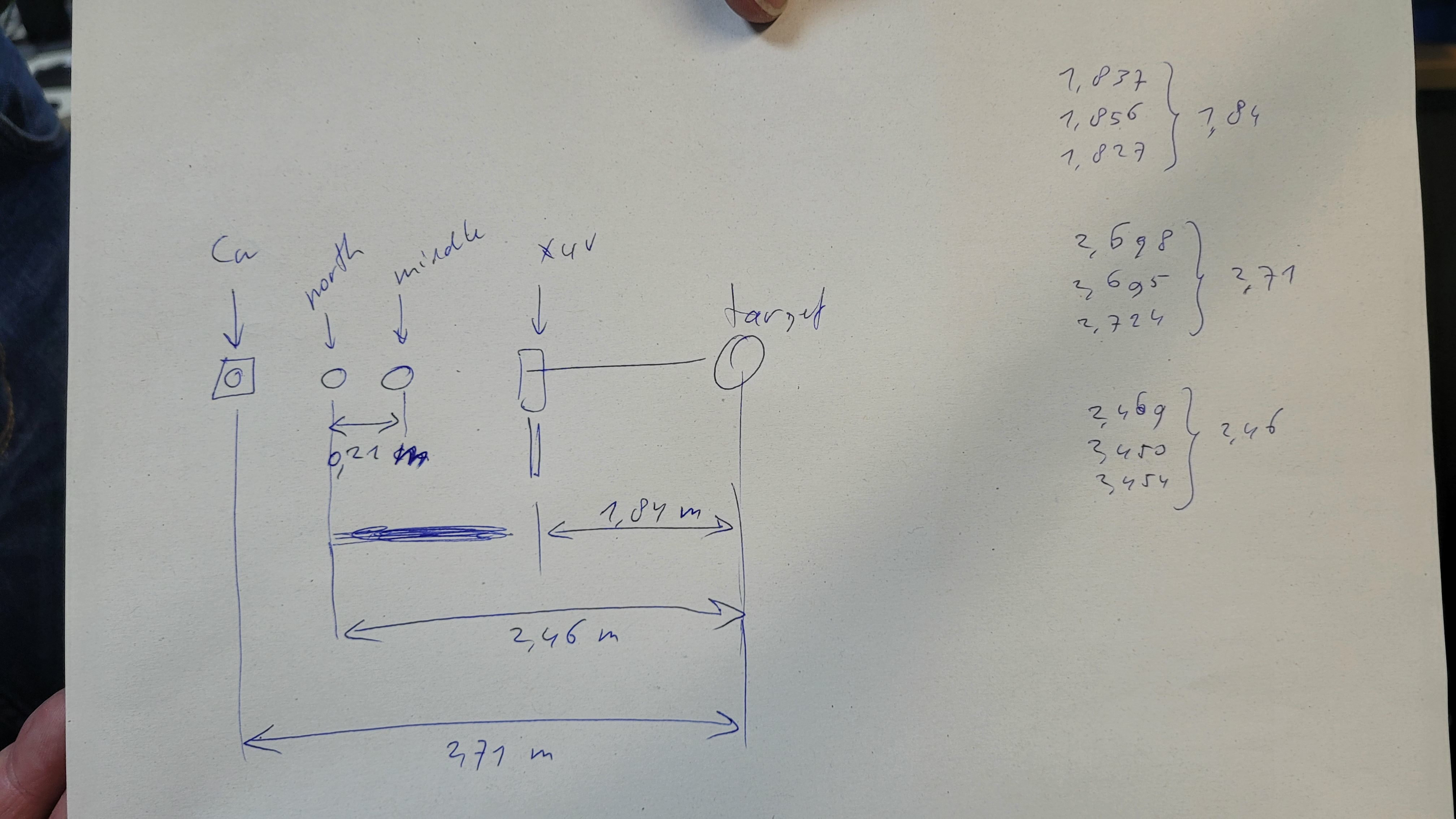
Relativ distances of the detector |
| Attachment 1: 20220407_164345.jpg
|
|