| ID |
Date |
Author |
Category |
Subject |
|
104
|
Mon Mar 30 23:30:35 2020 |
Jan | Analysis | run251 - Si-pad performance & status | Attached are plots for Si-pad 2 with hits from ionization of 206Pb81+ at the target.
The plots are representative for all Si-pads, the pattern is always the same!
y-axis: E n-side
x-axis: E p-side strip
condition: E_gate on peak in CsI
While strips 1, 2 and 7 look fine, strips 3 and 6 show already signs of degradation.
For strips 4 and 5, it is clearly visible that something is wrong.
Those are the central strips, which probably see the most rate.
The same dataset was analyzed here: https://elog.gsi.de/esr/E121/62
This might be a hint to a radiation damage or to the fact that we operate at too low bias voltage (32 Volt).
Maybe it recovers if we increase bias to 60 Volt. |
|
175
|
Thu Oct 1 22:20:03 2020 |
Jan | DAQ | final unpacker config | We identified an issue with randomly missing adc channels in all lmd-files before run 0273.
This led to errors in the unpacking process.
This issue is solved with the new config and mapping for the unpacker.
The respective files are attached here.
The unpacker is ready to use in /u/litv-exp/unpacker/unpackexps/E121
The adc issue is also understood. We deactivated the internal adc thresholds during the experiment, because we encountered the very same unpacker errors. This solved the problem for all later runs, but we forgot to think about a solution for the earlier runs.
Mea culpa.
Jan |
|
176
|
Mon Nov 2 16:45:55 2020 |
Jan | DAQ | f_user & mbslog | Attached is the f_user.c and the mbslog.l files.
The readout function is for the following setup:
3x ADC CAEN V785
1x SCA CAEN V830
1x TDC CAEN V1190
1x Vulom TRB5 (triggerbox)
1x Vulom4b PEV (priority encoder)
1x TRIVA7
1x RIO4 R4L-47 |
|
177
|
Thu Nov 5 15:13:43 2020 |
Jan | Analysis | root script example | Attached is an example root script/macro that shows how to use scripts for analysis.
Usage:
1. change INPUT and OUTPUT preprocessor variables in e121_analysis.c pointing to your desired input and output root-files.
2. open root and type: root [1] .L e121_analysis.C++
root [2] run() 3. check plots popping up and output files
Hints:
in e121_analysis.C use #include "e121_raw.h" for the original channel names/mapping (e.g. ADC1_1,...)
and use#include "e121_mapped.h" for named channels (e.g. e_csi[0] or e_dssd_top) |
|
178
|
Thu Nov 19 09:14:40 2020 |
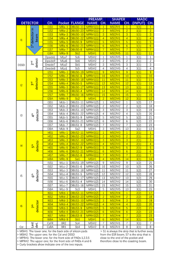
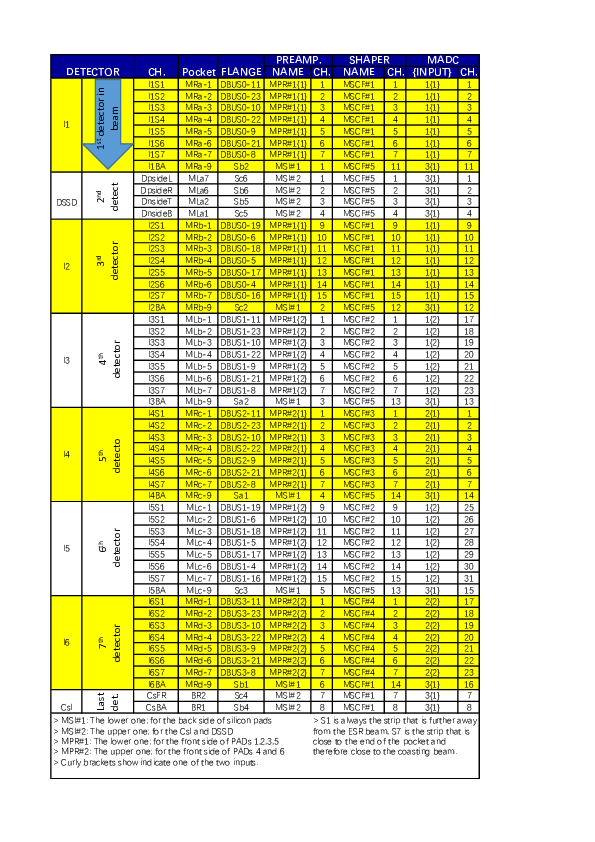
Jan | Detectors | remote MSCF settings for CsISiPHOS | Attached is a list of all set values for the 5 MSCF shaper modules.
This was done prior to run0251, which served as a final benchmark for those settings.
See: https://elog.gsi.de/esr/E121/62
And https://elog.gsi.de/esr/E121/104
The det. to MSCF assignment is the following:
MSCF 1: Si-pad 1 + 2 p-side/strips (ch. 1-7 + ch. 9-15)
MSCF 2: Si-pad 3 + 4 p-side/strips (ch. 1-7 + ch. 9-15)
MSCF 3: Si-pad 5 p-side/strips (ch. 1-7)
MSCF 4: Si-pad 6 p-side/strips (ch. 1-7)
MSCF 5: DSSD (ch. 1 - 4); CsI (ch. 7 & 8); Si-pad n-sides (ch. 11 - 16)
Note that only the pre-amplification stage of the MSI-8 amplifiers were used for all channels. |
|
180
|
Tue Dec 8 15:47:07 2020 |
Jan | Detectors | manual preamp & shaper settings for CsISiPhos | attached is a document showing fotos of all involved amplifiers in the chain to document the manual settings active during the experiment.
Summary:
Si-pad n-sides [MSI-8 (1)] were set to 5 GeV (expected E-deposition ~2 GeV)
Si-pad p-sides [MPR-32 (1 & 2)] were set to 1 GeV (expected E-deposition ~2 GeV)
DSSD channels [MSI-8 (2)] were set to 5 GeV (expected E-deposition ~1.2 GeV)
CsI channels [MSI-8 (2)] were set to 4 GeV (expected E-deposition 46 GeV)
It seems we got clipped signals from the Si-pad p-sides, because the MPR-32 were saturated due to a wrong gain setting.
This might explain, why there was not real influence on the spectra when adjusting MSCF settings for those channels.
I cannot comment on the CsI gain setting, because i don't know whether the given GeV-range by MesyTec directly applies for CsI & photodiode.
However, for DSSD and Si-pad n-sides the settings look okay. |
|
181
|
Tue Dec 15 09:25:41 2020 |
Jan | DAQ | SiCsIPhos signal/amplitude reconstruction | |
|
184
|
Wed Aug 25 15:13:41 2021 |
Jan | DAQ | SC13 clock frequency | The frequency of the clock used as reference in scaler channel 13 has been measured precisely.
In contrast to what was expected (1.5MHz precisely), it is:
f_ref = 1.5625(5) MHz |
|
2
|
Mon Dec 3 15:06:04 2018 |
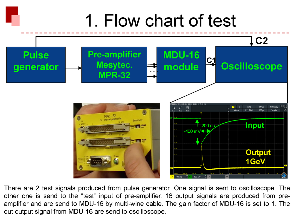
Chen, Sidhu | DAQ | Test of two preamplifier. | Description:
We have two pre-amplifiers:
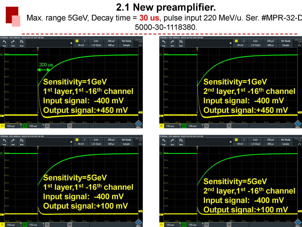
New: Max. range 5GeV, Two sensitivity options: 1 GeV and 5 GeV, Decay time = 30 us, pulse input 220 MeV/u, Ser. #MPR-32-D-5000-30-1118380.
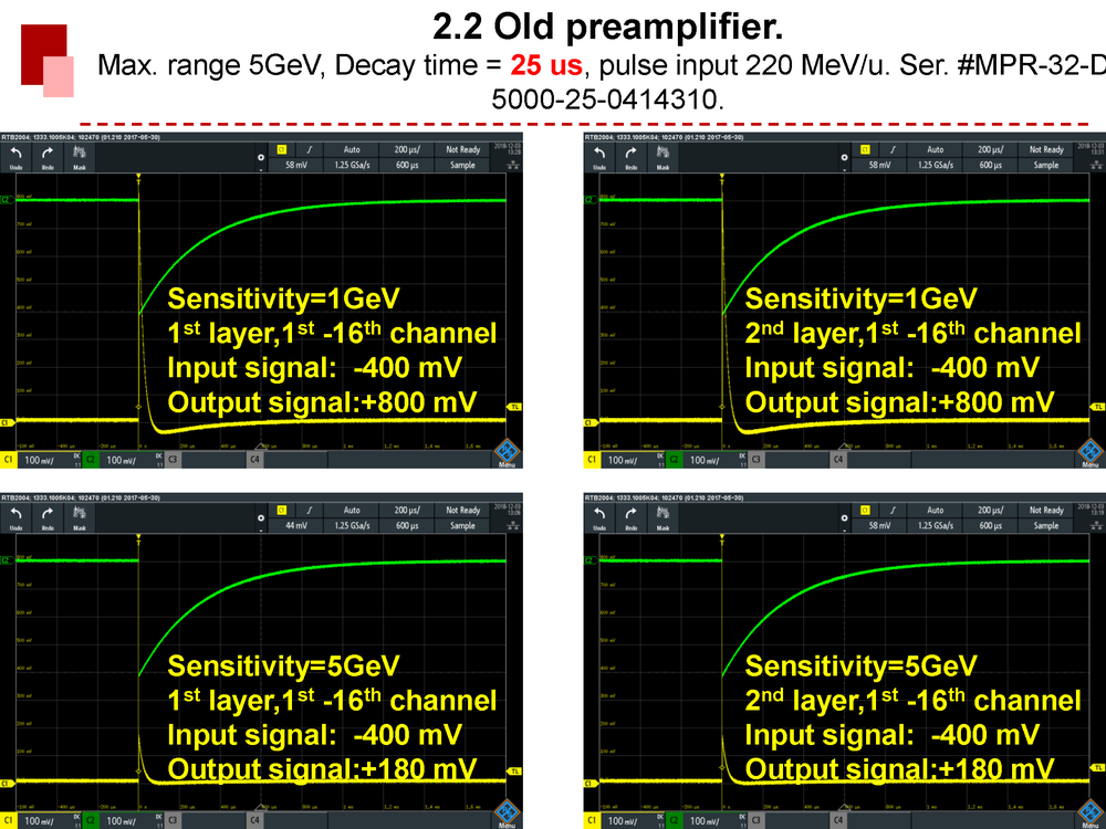
Old: Max. range 5GeV, Two sensitivity options: 1 GeV and 5 GeV, Decay time = 25 us, pulse input 220 MeV/u. Ser. #MPR-32-D-5000-25-0414310.
Conclusion:
Both pre-amplifiers work well.
The summary is attached in the followings:
 |
|
6
|
Mon Dec 10 11:59:15 2018 |
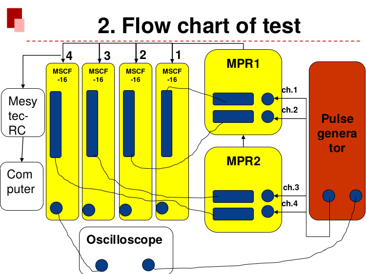
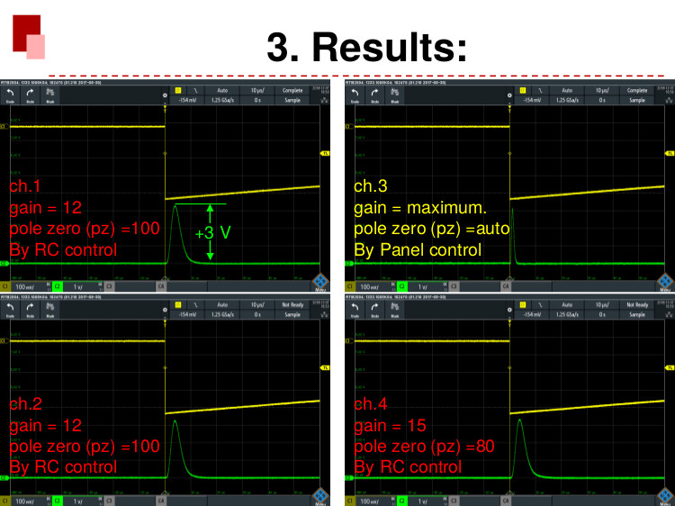
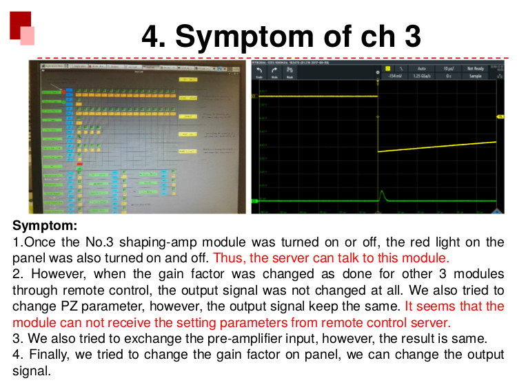
Chen, Sidhu | Detectors | Test of shaping amplifier. | 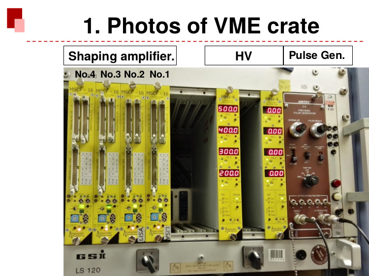
 |
|
7
|
Tue Mar 12 12:54:58 2019 |
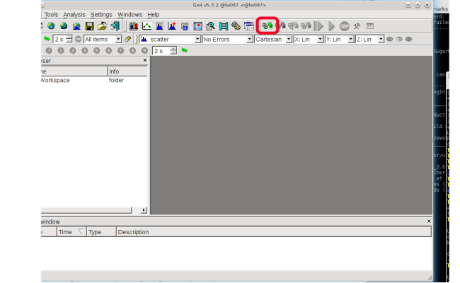
Chen, Sidhu | DAQ | how to start DAQ and plot histogram. | 1. login litv-exp account
rchen@lxg1254:/data.local2/2002_238UIMS$ ssh -X litv-exp@lxg0155.gsi.de
(don't login on lx-pool.)
litv-exp@lx-pool.gsi.de's password: ViValasVegas@****
2.login r4l-47 account
litv-exp@lxi087:~$ ssh r4l-47
litv-exp@r4l-47's password:ViValasVegas@****
3.start mbs
R4L-47 litv-exp > mbs
mbs>
mbs> -R4L-47 :msg_log :Message logger running
3.1 Initilizing, show, start and stop the acq
mbs> @startup
-R4L-47  ispatch :Task "m_util" not started! ispatch :Task "m_util" not started!
mbs> @startup
-R4L-47 :util :task m_util started
-R4L-47 :util :setup file setup.usf successfully loaded
-R4L-47 :util :trigger module set up as MASTER, crate nr: 0
-R4L-47 :util :enabled interrupt
-R4L-47 :collector  ipe type 2 or 4: virtual mapping ipe type 2 or 4: virtual mapping
-R4L-47 :transport :task m_transport started
-R4L-47 :read_meb ipe type 2 or 4: virtual mapping
-R4L-47 :transport :starting server in inclusive mode
-R4L-47 :transport :waiting for client (port 6000)
mbs> -R4L-47 :read_meb :task m_read_meb started
-R4L-47 :stream_serv:task m_stream_serv started
-R4L-47 :collector :task m_collector started
mbs> show acq
-R4L-47 ispatch :Task "m_util" not started!
mbs> show acq
-R4L-47 :util :--------------------------------------------------------------
-R4L-47 :util :ACQUISITION INITIALIZED 12-Mar-19 13:44:09: active tasks:
-R4L-47 :util :m_util m_transport m_daq_rate m_collector m_stream_serv
-R4L-47 :util :m_read_meb
-R4L-47 :util :SB setup LOADED from setup.usf.
-R4L-47 :util :Readout table NOT LOADED, acquisition STOPPED.
-R4L-47 :util :There are 32 streams with 32 buffers a 32768 each.
-R4L-47 :util :Current crate is 0, event builder is RIO4.
-R4L-47 :util :--------------------------------------------------------------
-R4L-47 :util :Crate 0: ID= 20, LOCAL SYNC SYNC , subevent slots=200000.
-R4L-47 :util : trig 1: cvt= 300, fclrt= 12 [usec], max se length=100000 b
-R4L-47 :util : trig 2: cvt= 300, fclrt= 12 [usec], max se length=100000 b
-R4L-47 :util : trig 3: cvt= 300, fclrt= 12 [usec], max se length=100000 b
-R4L-47 :util : trig 4: cvt= 300, fclrt= 12 [usec], max se length=100000 b
-R4L-47 :util : trig 5: cvt= 300, fclrt= 12 [usec], max se length=100000 b
-R4L-47 :util : trig 6: cvt= 300, fclrt= 12 [usec], max se length=100000 b
-R4L-47 :util : trig 7: cvt= 300, fclrt= 12 [usec], max se length=100000 b
-R4L-47 :util : trig 8: cvt= 300, fclrt= 12 [usec], max se length=100000 b
-R4L-47 :util : trig 9: cvt= 300, fclrt= 12 [usec], max se length=100000 b
-R4L-47 :util : trig 10: cvt= 300, fclrt= 12 [usec], max se length=100000 b
-R4L-47 :util : trig 11: cvt= 300, fclrt= 12 [usec], max se length=100000 b
-R4L-47 :util : trig 12: cvt= 300, fclrt= 12 [usec], max se length=100000 b
-R4L-47 :util : trig 13: cvt= 300, fclrt= 12 [usec], max se length=100000 b
-R4L-47 :util : trig 14: cvt= 300, fclrt= 12 [usec], max se length=100000 b
-R4L-47 :util : trig 15: cvt= 300, fclrt= 12 [usec], max se length=100000 b
-R4L-47 :util :--------------------------------------------------------------
-R4L-47 :util :Name of output device =
-R4L-47 :util :Tape label = , Dismounted, file CLOSED
-R4L-47 :util : 0.000 [MB] written to tape, 0.000 to file
-R4L-47 :util :--------------------------------------------------------------
-R4L-47 :util :Collected: 0.0000 MB, 0 Buffers, 0 Events.
-R4L-47 :util :Rate : 0 KB/s, 0 Buffers/s, 0 Events/s
-R4L-47 :util :--------------------------------------------------------------
mbs> start acq
mbs> stop acq
-R4L-47 :util :stop acquisition
mbs> -R4L-47 :collector :acquisition NOT running
-R4L-47 :read_meb :found trig type 15 == stop acquisition
4. plot the histogram
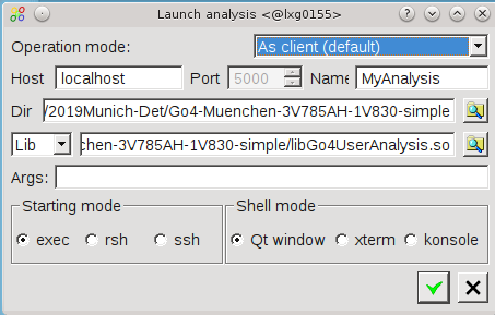
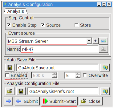
litv-exp@lxi087:~/2019Munich-Det/Go4-Muenchen-3V785AH-1V830-simple$ go4
Go4 v5.3.2, build with ROOT 6.12/06 and Qt 4.8.6
Using Qt settings at /u/litv-exp/.config/GSI/go4.conf (default)
 |
|
8
|
Tue May 7 15:52:47 2019 |
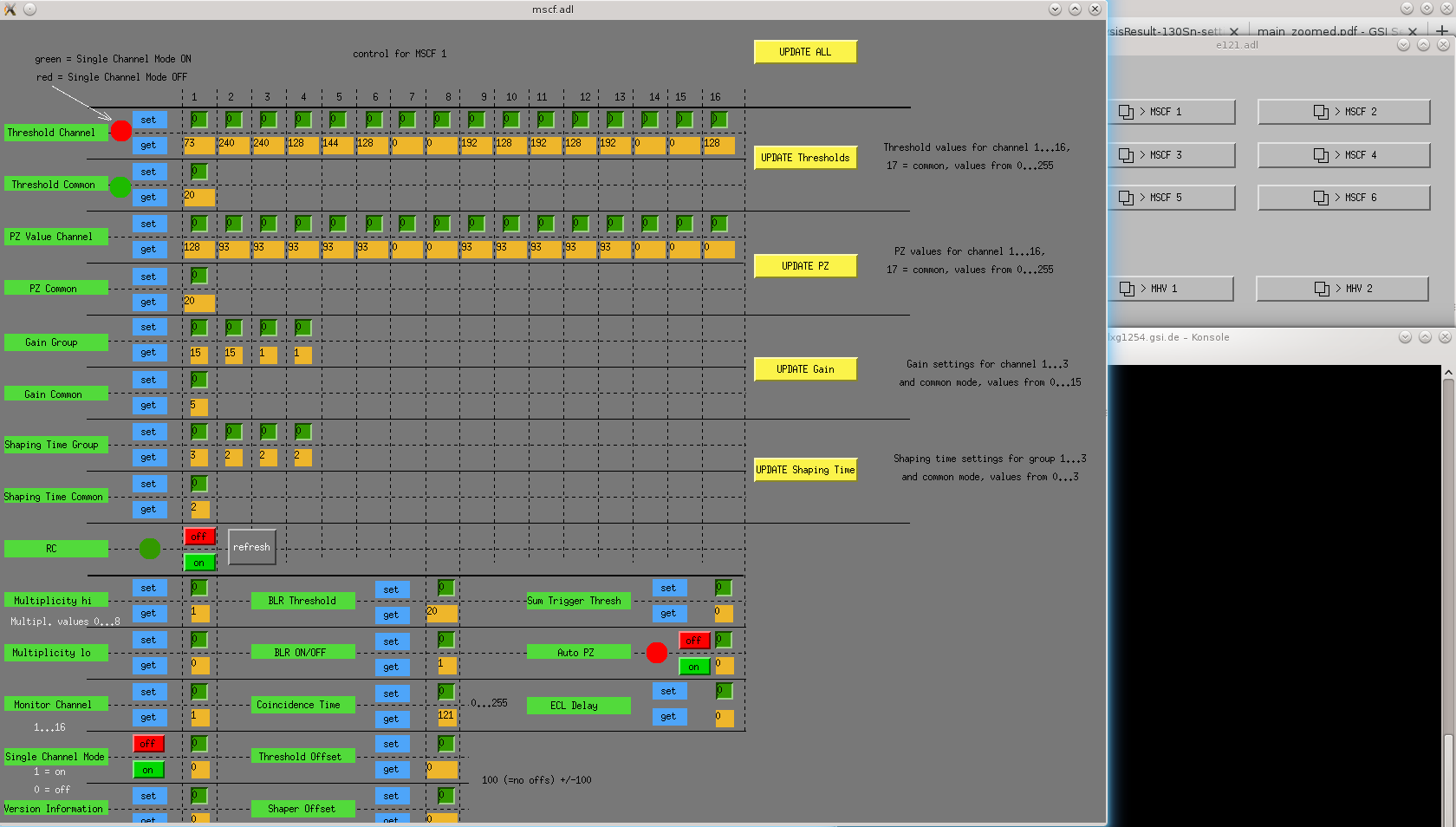
Chen, Sidhu | SlowControl | GUI for remote control of MSCF+MHV4 [detailed] | We have a GUI for remote controlling our MesyTec modules MSCF16 and MHV4 for E121 experiment.
Here is the instructions to run it:
1. login to GSI-linux using <litv-exp> user
litv-exp@astrum1:~$ ssh -X litv-exp@lxg1254.gsi.de
2. get the EPICS environment by typing in terminal: epicsfind
litv-exp@lxg1254:~$ epicsfind
Found nice EPICS in /u/litv-exp/epics/opt_x86_64-linux-gnu_4.9.2.
3. type in terminal: GUIe121 (alias for 'medm -x /u/litv-exp/E121/medm/e121.adl')
litv-exp@lxg1254:~$ GUIe121
if you get the message: 'medm: command not found' you didn't load the EPICS environment (1.)
The GUI is more or less self-explaining.
Be sure to follow this procedure when changing a value (e.g. threshold for MSCF):
1. click on small text-panel with value
2. leave mouse pointer inside panel
3. change value by typing
4. press enter |
|
11
|
Tue Aug 27 14:53:47 2019 |
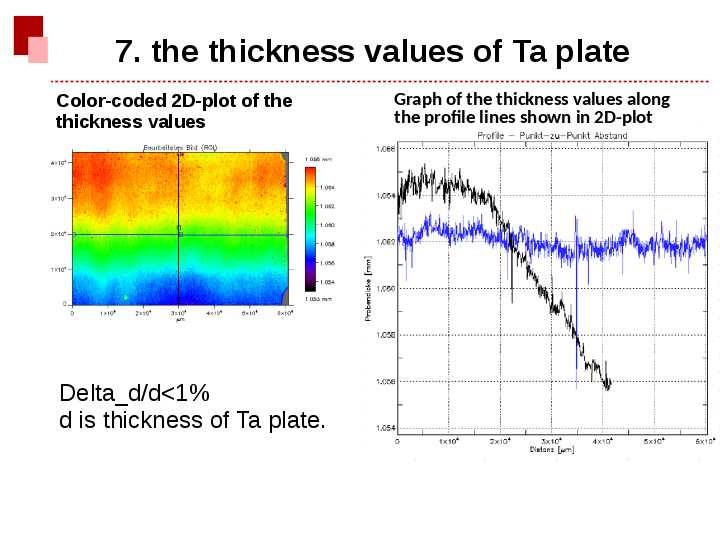
Chen, Sidhu | Detectors | The thickness uncertainty of Ta is less than 1%. | The thickness of Ta plate have been measured by target group. The result is show as following.
According to this measurement, the thickness uncertainty is less than 1%.
This thickness uncertainty is good enough for Tl experiment.
 |
|
12
|
Thu Oct 24 15:36:13 2019 |
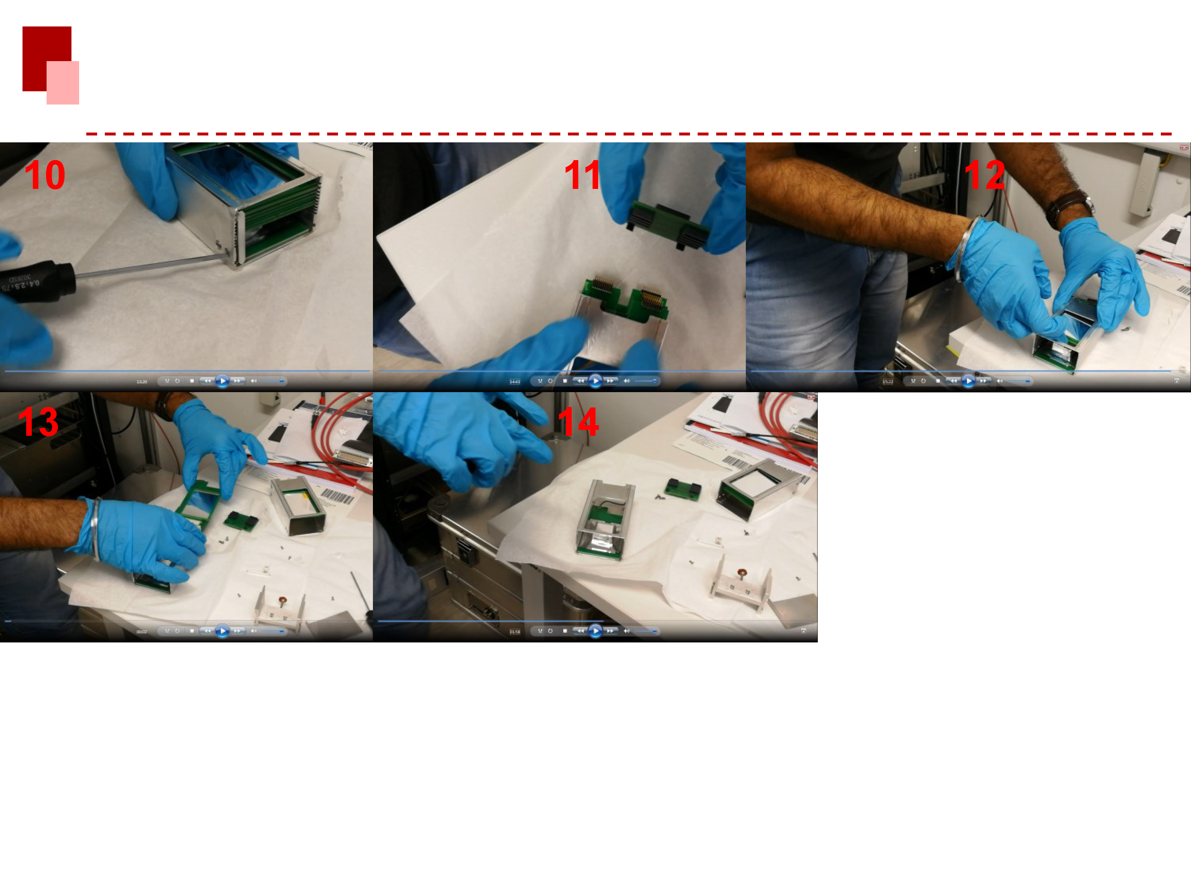
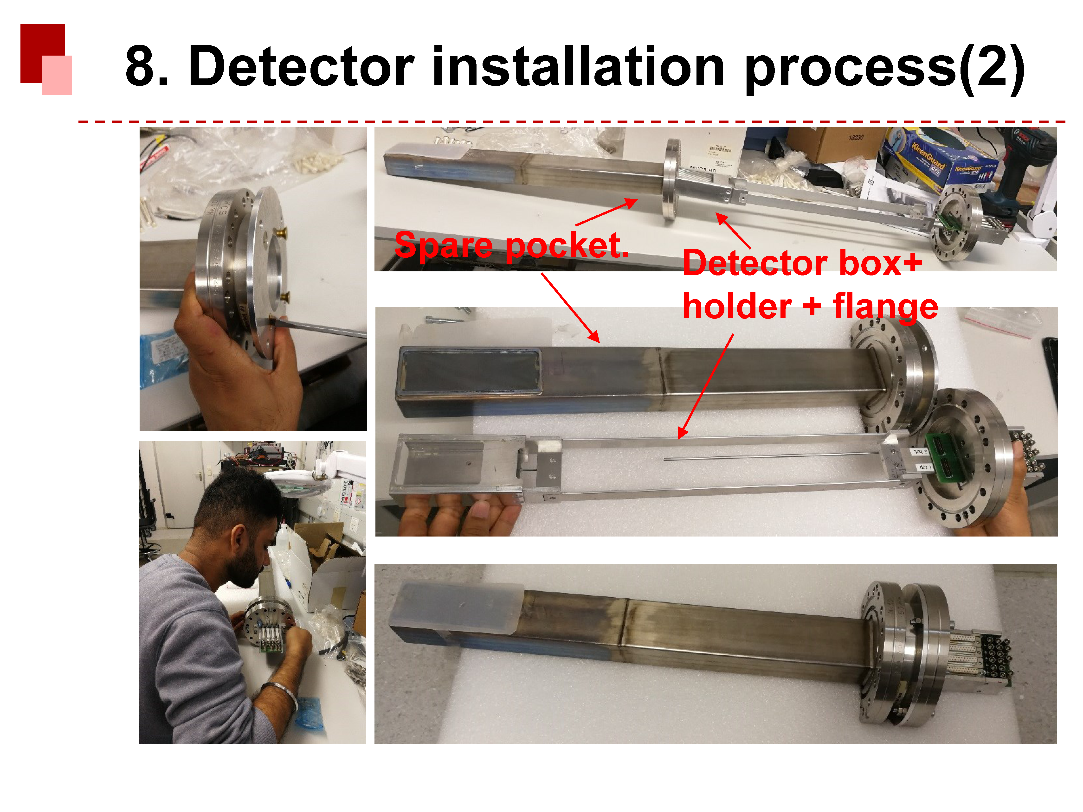
Chen, Sidhu | Detectors | Detector installation process | 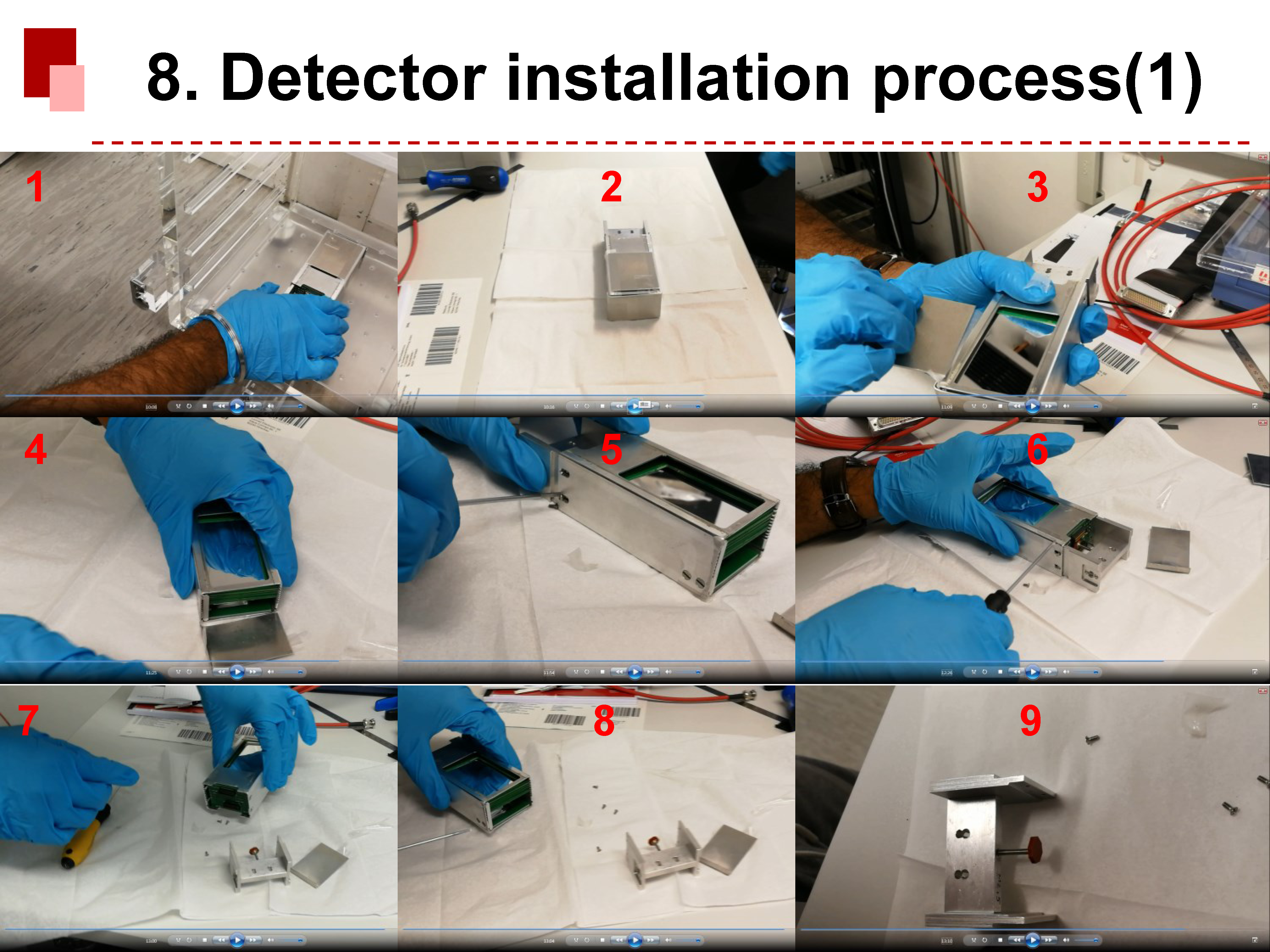
 |
|
43
|
Sat Mar 28 18:11:13 2020 |
Alex, Yuri | General | no beam in the ESR | Yuri and Sergey (on phone) have investigated extensively the problem with having no beam in the ESR. The FRS has been checked and seems OK. The ESR is fine as well.
The problem seems to be the timing. Ths SIS and the ESR seem to be completely out of synchronization. The on-call service for the control system has been called. |
|
39
|
Sat Mar 28 15:23:05 2020 |
Alex, Ragan, Mei Bai | General | beam lifetime measurement | We see two species in the Schottky spectra during the beam lifetime measurement without the target. The one (probably the primiary beam) is significantly better cooled than the other.
So, we were wondering what is the other beam? Maybe the recombined ones? |
|
152
|
Sat Apr 4 22:31:02 2020 |
Alex, Esther | General | Beam in ESR lost | The beam in ESR was lost suddenly at ~22:20 due to a power supply failure of the quadrupoles.
Update (~20:40): Failure was resolved and new stacking started. |
|
40
|
Sat Mar 28 16:09:50 2020 |
Alex | General | no beam in the ESR | Ragan and Ruijiu went in the ESR for short time to fix something with the slow control of the silicon detector.
After this, there is no beam in the ESR. |
|
3
|
Wed Dec 5 17:29:24 2018 |
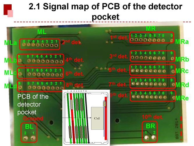
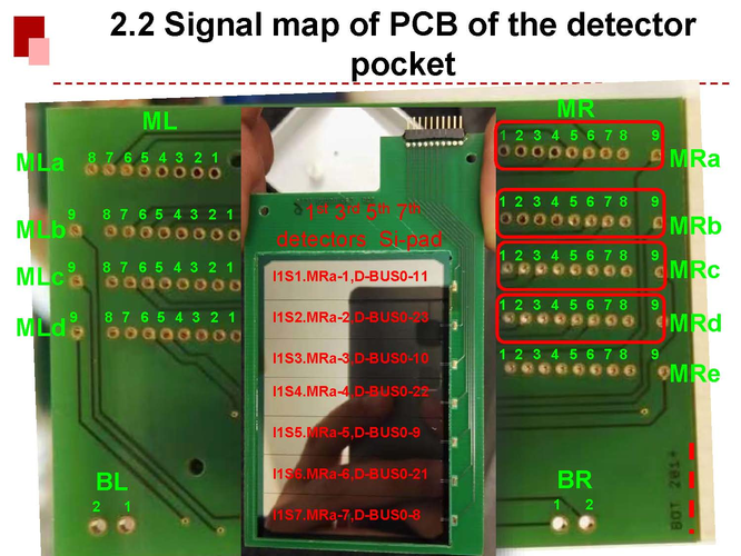
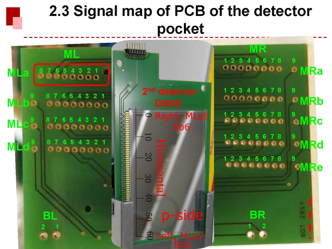
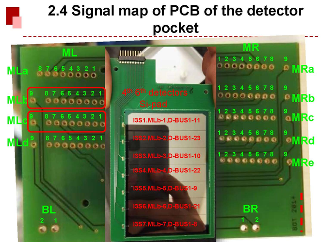
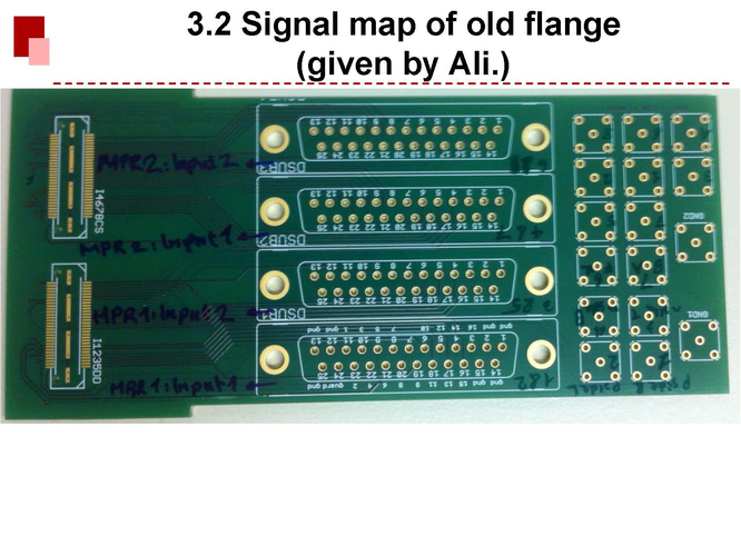
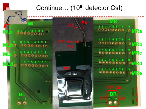
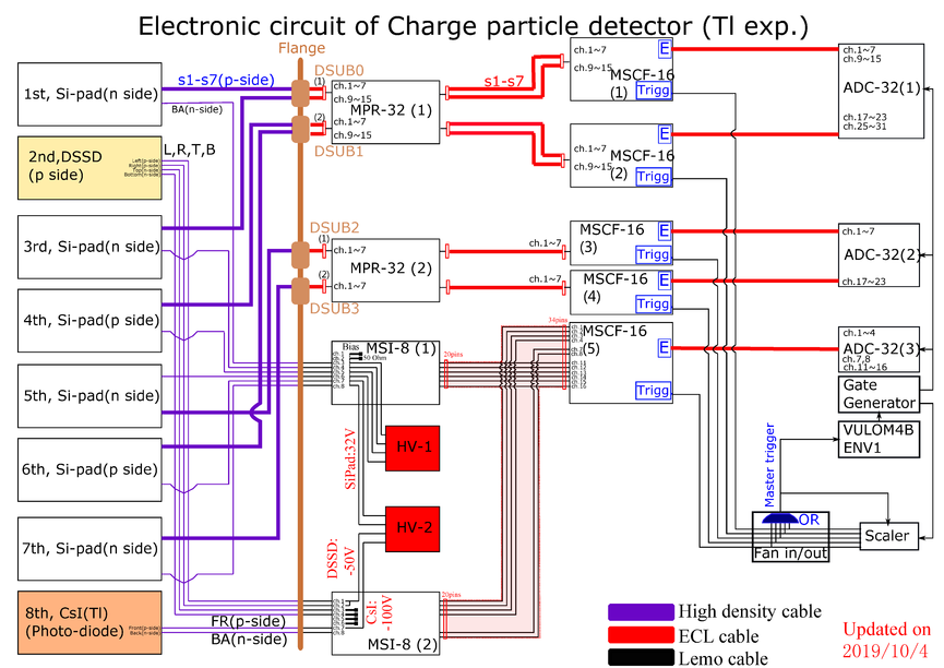
Chen, Sidhu | Detectors | signal map | Description:
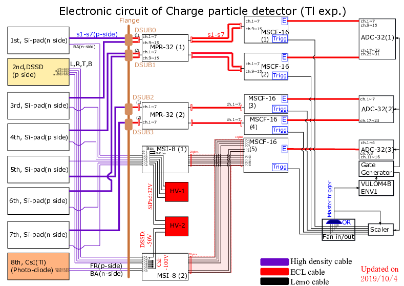
Here is a summary of signal map. The charged particle detector includes 6 layers of Si-Pad, 1 DSSD and 1 CsI.
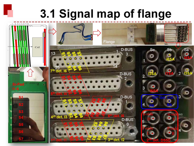
All these detectors are installed inside the detector pocket. All signals are connected to one PCB which is attached on the pocket, then are connected
to the PCB of the flange by high density cable. This document descripts the signal map on the PCB of the detector
pocket and flange.
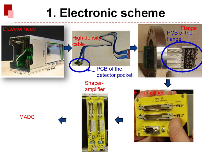
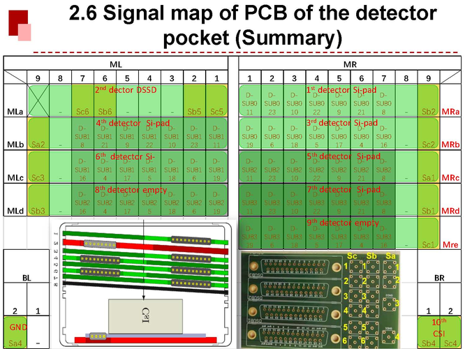
The signal maps of the PCB of the detector pocket are shown as follow:
 |
|
52
|
Sun Mar 29 13:43:46 2020 |
| | | |
|