| ID |
Date |
Author |
Category |
Subject |
|
63
|
Sat Apr 2 05:08:00 2022 |
Kristian | General | Morning shift |
I see no updates in the log. Is the morning shift taking place?

For now I will stay at home and be on call. I can be at GSI in 20 min. Please let me know the status.

01575 8731537 |
|
97
|
Tue Apr 5 13:24:40 2022 |
Kristian | Detectors | PMT Cu |
HV cable was in wrong channel in power supply. Now it is back to the correct position. Checked connection at the PMT. |
|
98
|
Tue Apr 5 13:28:06 2022 |
Kristian | DAQ | Spikes in PMT signal |
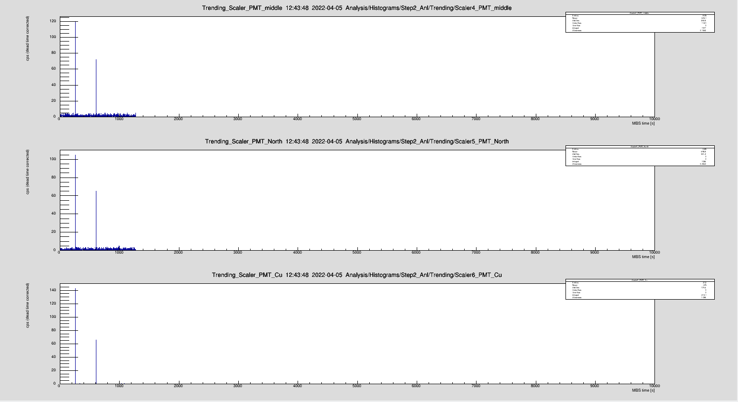
Occasionally, we noticed a spike in the PMT signal. No ions in the ring and at PMT Cu was not even supplied with HV. Has to be some electronic pickup |
| Attachment 1: spike.png
|
|
|
99
|
Tue Apr 5 14:51:51 2022 |
Kristian | DAQ | dark counts |
We shielded the PMTs, i.e., the N2 tube, which improved the Cu PMT background rate.

Without beam and ESR lights off:

PMT Mitte: 4 Hz
PMT Nord: 1 Hz
PMT Cu: 240 Hz |
|
160
|
Fri Apr 8 11:16:57 2022 |
Kristian | Laser | Wavemeter |
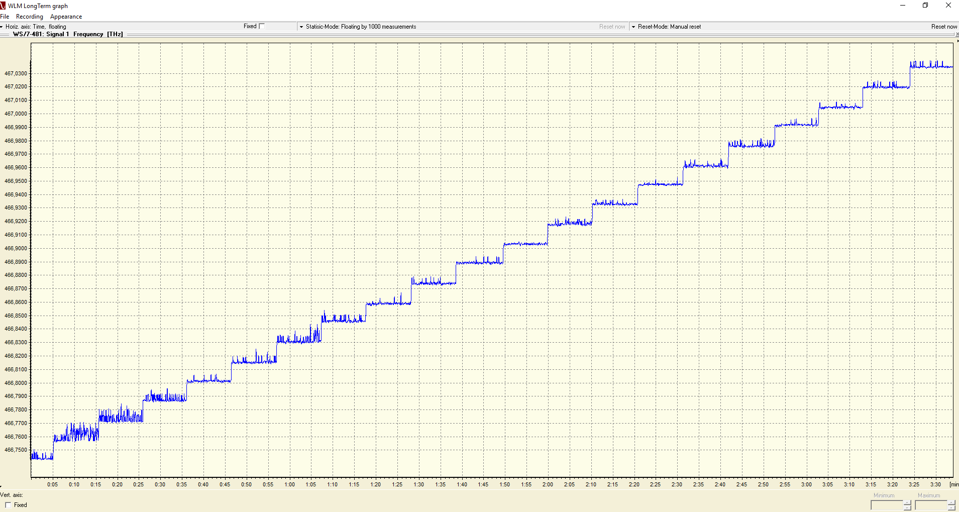
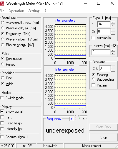
We changed the fiber to the wavemeter. The third fiber worked best and we could operate the WM at low exposure times, i.e., below the laser repetition rate. We used the neutral density filter to adapt the laser power that only one laser pulse is measured by the WM each time (Exposure time =34ms)

This way, there are no frequency jumps. The jitter is slighly different at each wavelength which was ~5GHz peak to peak.


We optimized the fiber coupler and slightly optimized the jitter to <4GHz. |
| Attachment 1: Wavemeter.PNG
|
|
| Attachment 2: Wavemeter2.PNG
|
|
|
163
|
Fri Apr 8 14:14:28 2022 |
Kristian | DAQ | Delay of bunch RF |
The bunch HF is now fed through a delay to shift the stop trigger relative to the PMT signal. The delay generator is placed directly after the CFG and before splitting the signal for the two DAQs. The relative timing of both DAQs was not changed. |
|
182
|
Sat Apr 9 06:42:23 2022 |
Kristian | Laser | Laser step size |
We changed the laser step size to 0.002 nm which corresponds to 5.75 GHz. |
|
209
|
Mon Apr 11 12:50:22 2022 |
Kristian | Accelerator | Th lifetime |
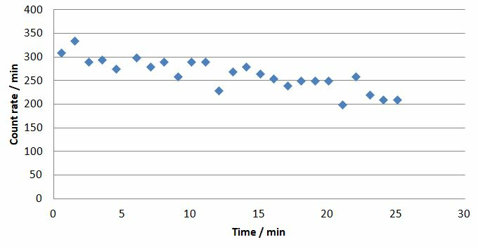
We used the counter to measure the lifetime. During the 30 min scan time dropped only slowly.

During a longer break, e.g., when the laser flash lamps are changed, one could take data over a longer time. |
| Attachment 1: ThLifetime.JPG
|
|
|
213
|
Mon Apr 11 22:14:51 2022 |
Konstantin, Sarper | Laser | Changing of the wavelength range |
It is planned to change the scan range of the laser wavelength from 322.41 - 322.0 nm to 322.01 - 321.6 nm @ 4 a.m. |
|
143
|
Thu Apr 7 19:13:26 2022 |
Konstantin, Patrick | Calibration | How to find the correct laser position |
In order to achieve the correct laser ion beam superposition one needs to do the following steps:
- If the laser stabilization is still running, turn both stages off and block the main amplifier.
- Ensure that the laser spot is centered on the paper screen, which is located in top of the laser tower in the south (ATTENTION: please only use the preamplifier and not the main amplifier!!! If you're unsure what you are doing please contact Rodolfo or Konstantin).
- If this is not the case and the beam is completely off, have a look at the MRC Stabilization system. If it is running, close the software and turn the hardware off and on again. The spot will leave its position and come back after the stabilization is turned on again.
- If it is still not centered, use and only use the piezo mirror (the one with red screws) to bring back the spot.
- Remove the paper screen and then turn on the main amplifier.
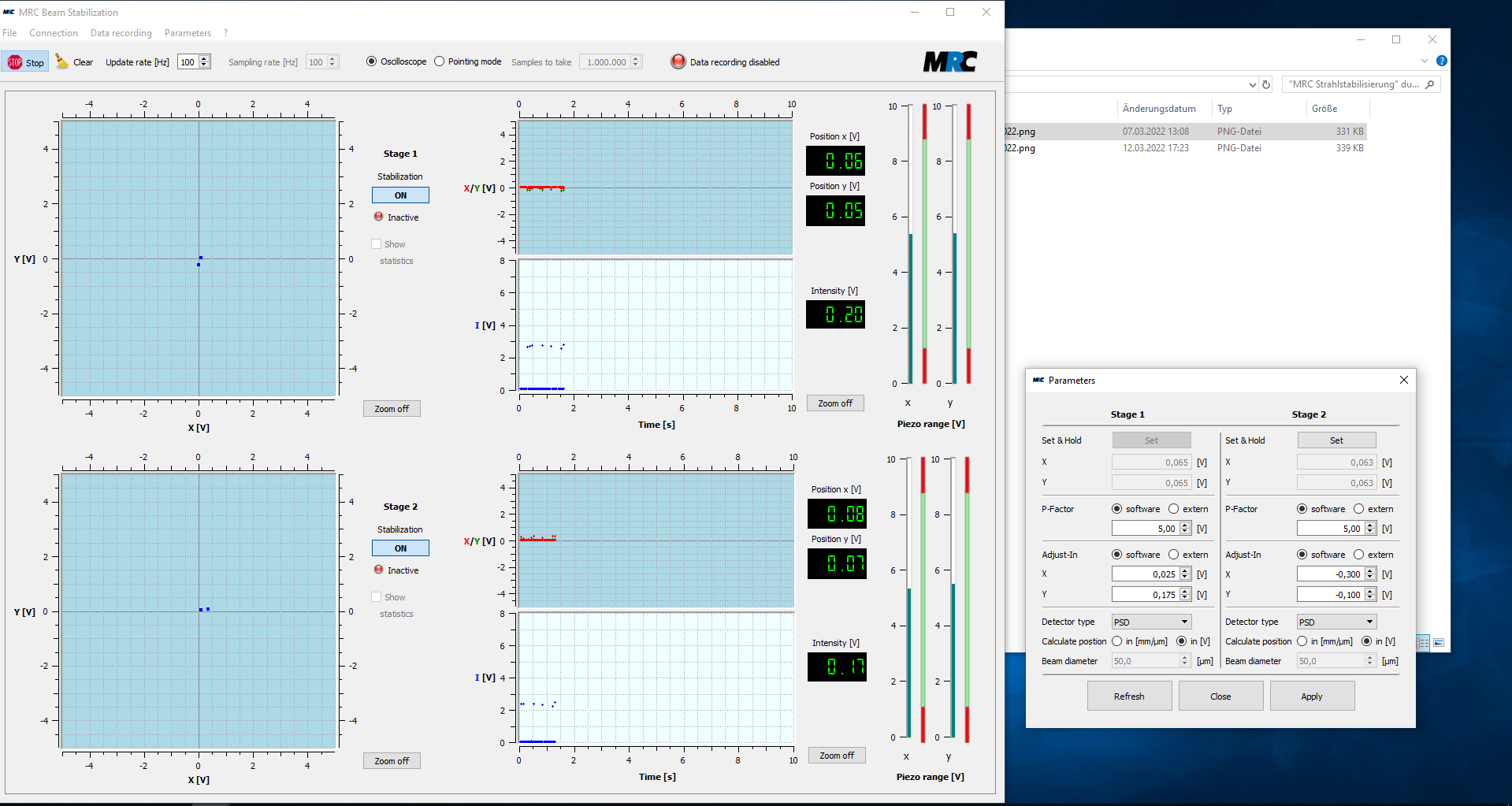
- Restart the software and put in the values from the file 07-04-2022(...).png. Start the two stabilization stages in the software. The laser spot should move back to the correct position.

|
|
82
|
Sun Apr 3 18:41:11 2022 |
Konstantin and Rodolfo | Laser | Beam Position Stabilization |
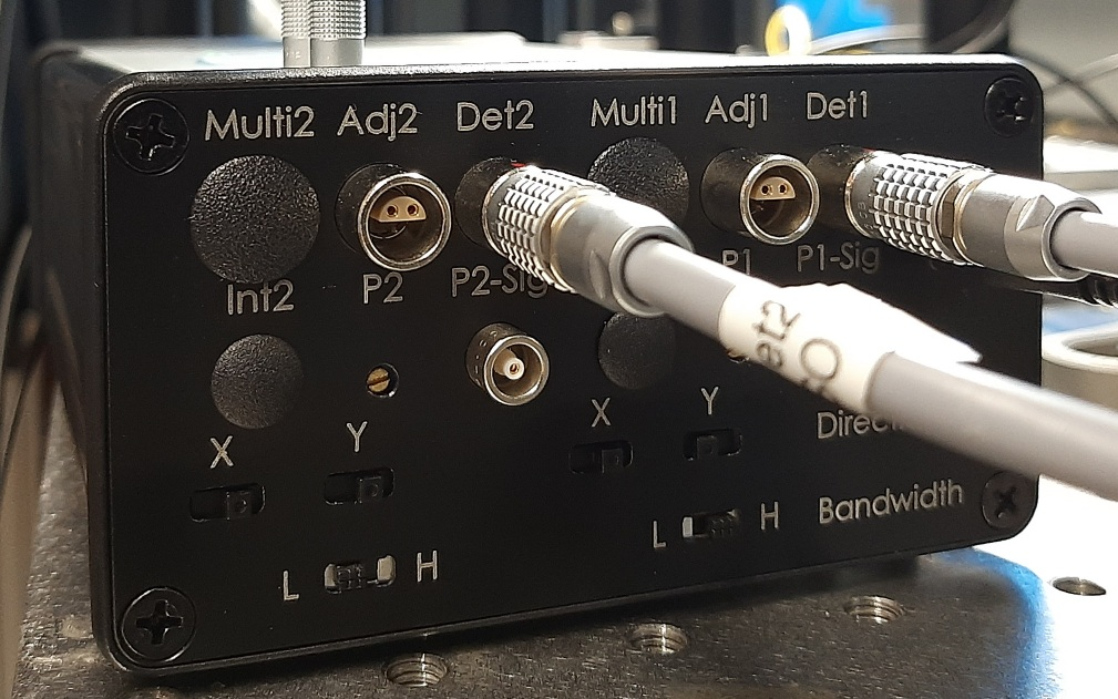
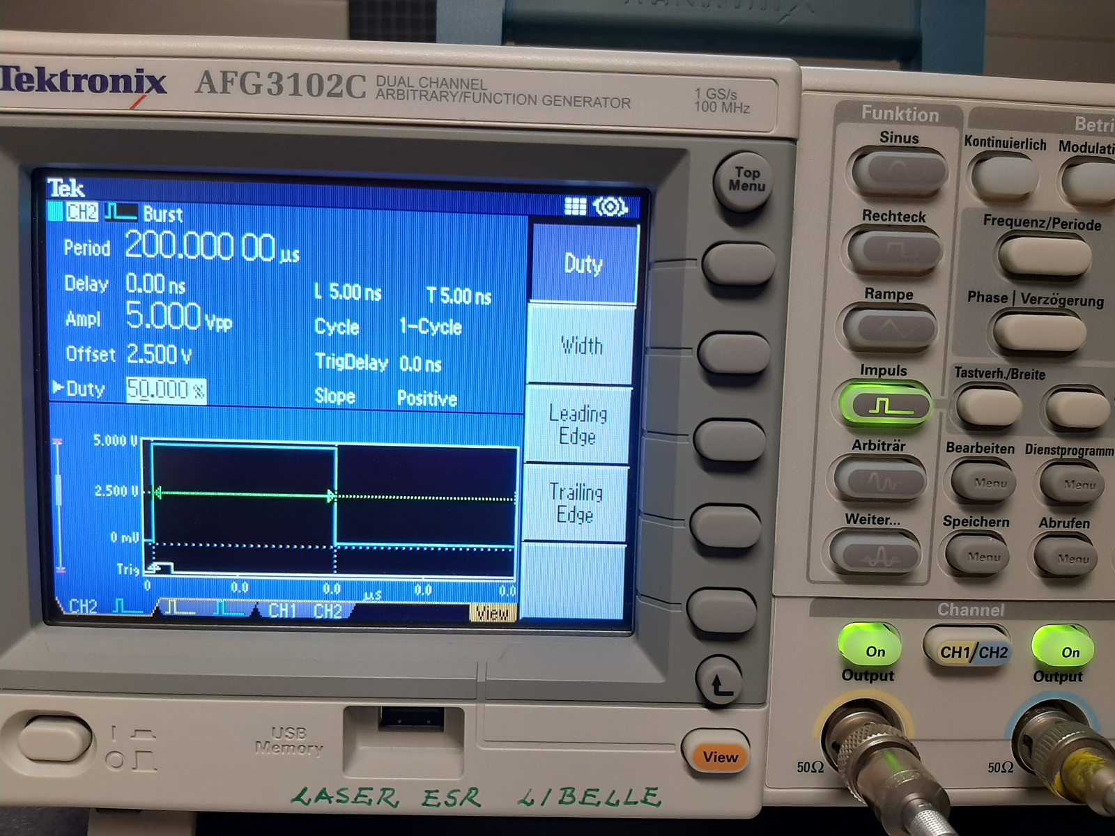
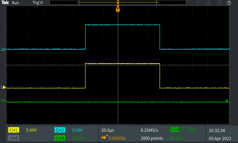
We (Konstantin and I) have optimized the TEM "laser-beam position stabilization".
- I took some pictures (screenshots) about the current setting*.
- In order to be able to move the laser position faster we increase the P-Factor of both stages to 5 (maximum value).
- In "TriggerSignals_f_MRC_04-04-2022" the fast PD defines the origin (t = 0 s). |
| Attachment 1: MRC_Konfiguration_MitMainAmp_03-04-2022.png
|
|
| Attachment 2: MRC-ControllerSetting_03-04-2022.jpg
|
|
| Attachment 3: FG_SettingsMRC_03-04-2022.jpg
|
|
| Attachment 4: TriggerSignals_f_MRC_04-04-2022.PNG
|
|
|
40
|
Thu Mar 31 11:49:54 2022 |
Konstantin | Detectors | HV-Supply of particle detectors |
| We cross-checked the cabeling of the particle detectors north and south. Particle detector south is connected to channel HV5 at the yellow "ESR Messplatz III" patch-panel. Particle detector north is connected to channel K5 at the green "ESR Messplatz II" patch-panel. Red high voltage power-supply is used to control the voltage. |
|
42
|
Thu Mar 31 15:53:50 2022 |
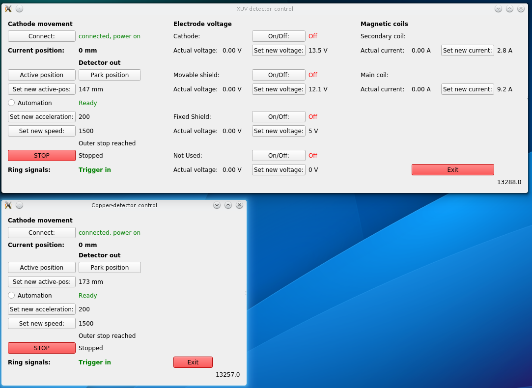
Konstantin | Detectors | Control software for XUV and copper mirror detector |
> Attached you find a manual for the software used to control the movement of the XUV detector and the copper mirror detector.
> The software is also used to set the electrode voltages and coil currents of the XUV detector.

We tested the remote access to the raspberry pi as explained in the manual attached to the original entry of Volker. It was tested from
the linux machine LXG1050. Attached you can find a screenshot of the running program. |
| Attachment 1: XUV_Cu_GUI.png
|
|
|
43
|
Thu Mar 31 17:56:32 2022 |
Konstantin | DAQ | Photodiode test signal |
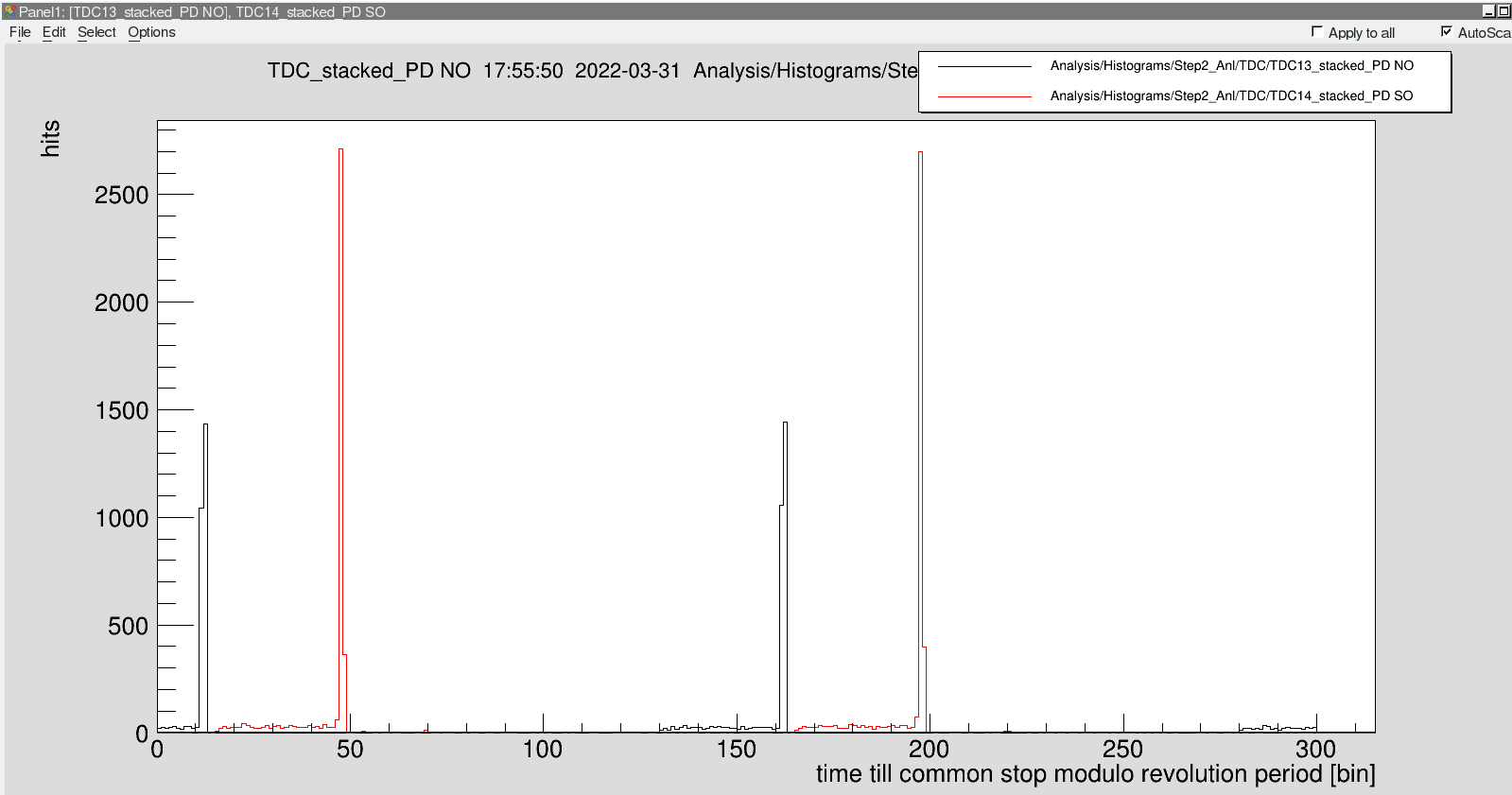
| We used a signal generator to provide a 4MHz dummy-RF signal. This was divided by a factor of 2 for laser-"bunch" synchronization and by a factor of 200 for to provide the stop-tigger attached to the DAQ. With this Dummy-RF we were able to measure the relative arrival times of the laser at the photodiodes located in the laser towers. Note that the signal of the southern photodiode arrives first. This is because the scale of the time axis is given in (10/3ns)-bins since the last common-stop. |
| Attachment 1: Timing_Photodiodes.png
|
|
|
58
|
Fri Apr 1 22:01:14 2022 |
Konstantin | Detectors | PMT operating voltages |
> During the testing of the PMTs the following operating voltages were applied:
>
> PMT Cu: -1300V
> PMT Nord: -2500V
> PMT Mitte: -1800V
> PMT Süd: -1800V
>
> Further optimization will be necessary during background measurements.
Currently, PMT Süd shows a strange behavior resulting in after-pulses up to 1µs. Therefore, the high-voltage was reduced to -1500 V.
However, the after-pulses remain. This should be investigated in more detail at some other point. |
|
83
|
Sun Apr 3 18:52:30 2022 |
Konstantin | Calibration | Laser ion beam overlap |
We measured vertical and horizontal ion beam positions. Unfortunately, the horizontal scraper positions can not be manipulated
by the "Device Control" software. Robert Boywitt has supported us a lot to get the drives moving by using the expert software on
a local control PC, which can only be remotely accessed from beapc032 with the usual experiment account "atplaser". In the first
try we were only able to determine the vertical positions of a beam which was not the 229Th (positions were measured already on
Sunday, 03.04.)
|
Scraper | ion beam position (outer->inner) | |
GECEDS2VU | -1.3(2) mm | |
GECEDS1VU | -0.7(2) mm | |
|
Finally, we got 229Th (Wednesday, 06.04.) and were able to measure the ion beam positions. Those are
summarized in the following table. The first values are those were the scraping begins, hence representing the
edge of the ion beam. The second values represent the central positions of the ion beam.
|
Scraper | ion beam position (outer->inner) | ion beam position (inner->outer)
| |
GECEDS2VU | -1.6(2) mm / -1.3(2) mm | | |
GECEDS2HA | -13.8(2) mm / -13.4(2) mm | -4.0(2) mm / -4.6(2) mm | |
GECEDS1VU | -1(4) mm / -0.9(2) mm | | |
GECEDS1HA | -18.1(2) mm / -17.6(2) mm | -7.7(2) mm / -8.2(2) mm | |
|
Schreenshots taken at scraper positions are given in Entry 142 |
|
142
|
Thu Apr 7 16:50:22 2022 |
Konstantin | Calibration | Spacial laser-ion overlap |
Laser-ion-beam overlap was achieved after measuring the ion beam positions (compare Entry 83).
Screenshots are comprised in the following table.
|
|
169
|
Fri Apr 8 17:44:25 2022 |
Konstantin | Calibration | Final Timing |
We measured the timing for the laser bunch synchronization. A summary is given below.
|
detector | time till common stop [bins] | time till common stop [ns]
| |
PD North | 28 | 93.33 | |
PD South | 63 | 210 | |
Particle Detector South | 14 | 46.67 | |
Particle Detector North | 94 | 313.33 | |
PMT middle | 119 | 396.67
|
Using all numbers, the difference between the center of the photodiodes and PMT middle is
given by 245ns, which corresponds to the half revolution period of 256 ns. Difference between the
center of both photodiodes and particle detector south is given by 105 ns.
The delay for the laser trigger is now set correctly. |
|
170
|
Fri Apr 8 17:57:45 2022 |
Konstantin | DAQ | Laser scanning |
|
Time | SIS-intensity | cooler-HV | LMD-DAQ1 (R4L-68) | LMD-DAQ2 (R4L-41) | scan range (nm) | step width(nm) | dwell time(s) | comments
| |
17:28 | 1.1e9 | - | 0083 | 7822 | 322.3-321.3 | 0.01 | 4 | Wrong scan range
| |
17:48 | 1.4e9 | 209618 | 0084 | 7823 | 322.3-321.3 | 0.01 | 4 | Wrong scan range
| |
18:10 | 1.6e9 | - | 0085 | 7824 | 323.2-321.2 | 0.01 | 4 | acquisition on r4l-68 crashed
| |
18:13 | 2e9 | - | 0086 | - | 323.2-321.2 | 0.01 | 4 | acquisition on r4l-41 crashed
| |
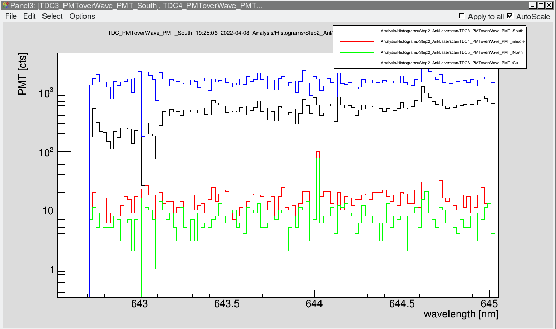
18:29 | 1.9e9 | 209618 | 0087 | 7826 | 323.2-321.2 | 0.01 | 4 | An artifact is observed at about 644nm <-> 322nm fundamental wavelength
| |
20:17 | 2e9 | 209609 | 0089 | 7827 | 323.2-321.2 | 0.01 | 4 | Cu-mirror and XUV detector are not driven at the moment. It is unclear for how long this was the case. Optimization of the accelerator settings were done before.
| |
21:12 | 1.6e9 | - | 0089 | 7828 | 323.2-321.2 | 0.01 | 4 | Laser got wrong pulse widths during this scan and also during the last one.
|
At about 20:00 the slits were adjusted to the h=1 settings:
NI: 5mm
NA: -3mm
SA: -10mm (also the voltage for the Scitnilator in this pocket was increased to 1500V)
SA_Scraper: +14mm |
| Attachment 1: Artifacts_in_PMT_MiddleAndNorth.png
|
|
|
221
|
Tue Apr 12 17:01:30 2022 |
Konstantin | Detectors | Voltage PMT North |
| Voltage of PMT North has been increased from 2500 V to 2600 V. Additionally the threshold was adapted from 25 mV to 12 mV. |