| ID |
Date |
Author |
Category |
Subject |
|
54
|
Fri Apr 1 15:52:23 2022 |
Rodolfo | Detectors | UV PMT South |
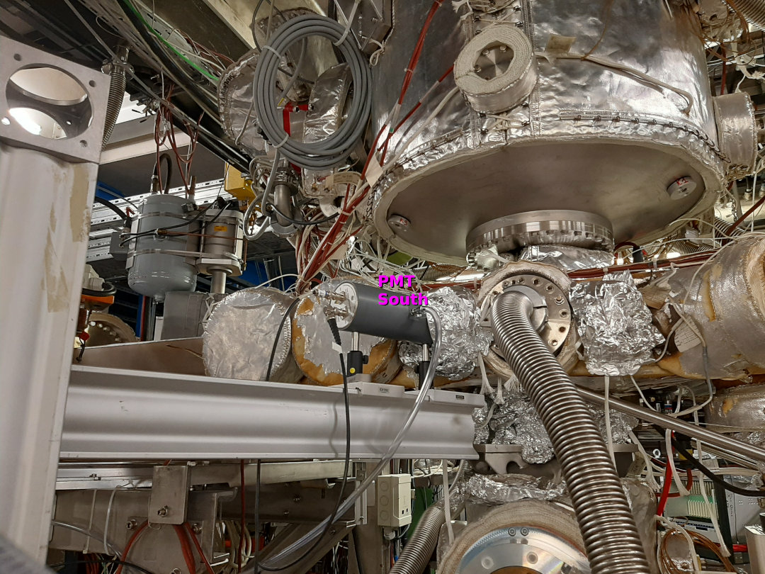
The "Solar Blind PMT" labeled as "PMT South" has been installed by Simon and Max in the gas target chamber on a CaF Viewport. The PMT is pointing directly to the center chamber.
- I have covered the support of the PMT and the flange with additional aluminum foil in order to try to reduce the straight light.
- I will check the signal of the PMT as soon as the lighting inside the cave will be turned off.
Bild: R. Sánchez |
| Attachment 1: PMT_Sued_Target.jpg
|
|
|
102
|
Tue Apr 5 20:58:53 2022 |
Wilfried | Laser | Trigger for Laser |
Electronic for the timing of the laser puls optimized. The problem with the broad photodiode histograms is solved.
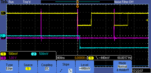
The photo of the oscilloscope picture shows in magenta the pulses from the (discriminated RF)/2, in yellow the pulses that are generated to open the Q-Switch. The latter are generated by the coincidence of the 30-Hz trigger (2 microsec long) to
allow for the Q-Switch to be fired. Within this period are usually 2 pulses from the RF and both generate a 100 ns long coincidence puls. The first one of those creates a 50 microsec long window (light blue) that is send to the Q-switch. The length
and the delay of this pulse can be changed. While the length is kept fixed, the delay can be changed in order to shift the arrival time of the laser pulse at the electron cooler to coincide with the ion bunch.
The problem of the wide photodiode histograms and the background was caused by a too large pulsewidth of the discriminated RF. The magenta pulses were about 100 ns long. Any pulse that arrives within a timespan between 99 and 0 ns before the 30-Hz
trigger of the Q-switch "allowance" will trigger a laser pulse immediately at the start of this trigger and therefore a jitter of up to 100 ns can occur. Therefore it is important that the CFD pulses are as short as possible, we set them to 20 ns
and the width of the photodiode histogram was just 3 bins wide (at the foot maybe 5 bins).
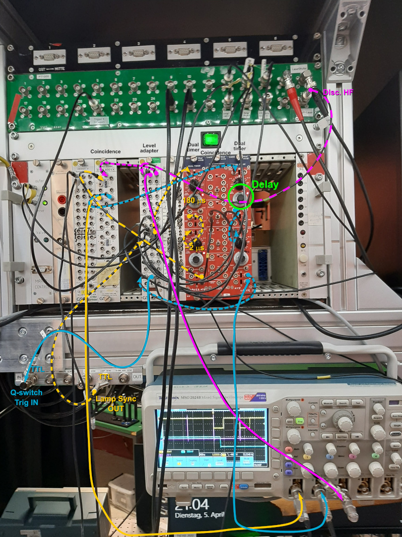
I (Rodolfo) just added the picture with the cabling configuration. The colors of cables match together with the colors show in the oscilloscope. |
| Attachment 1: TriggerForLaser_05-04-2022.PNG
|
|
| Attachment 2: TriggerLaser_Cabling.jpg
|
|
|
126
|
Thu Apr 7 04:48:58 2022 |
| | ToDo's for 07.04. |
Some ToDo's for the next shift:
- Work on  Laser stabilisation 2nd stage in the ESR
- Mesytec power supply of the xuv-detector crashed and needs to be restarted in the ESR. Simply turning it the crate off and on again)!!
- Fix wavemeter fluctuates
- Compare MBS event size of DAQ 1 ("by laser group") and DAQ 2 ("by Carsten"), DAQ 1 data size was ~2 times larger than DAQ 2 data size.
- Use lmd-files measured last night to test Go4-Analysis.
- Practice measurement procedure with beam, see Message ID: 124. |
|
196
|
Sun Apr 10 08:53:26 2022 |
Kristian, Max | Laser | Timing verified |
timing is still good.

we checked the relative timing between laser and ions. the time difference between photodiodes, PMTs and particle detectors is still the same as original (see ELOG ID 169). The common stop of changed a slightly so that everything appears one bin later. |
|
49
|
Fri Apr 1 01:57:12 2022 |
Kristian | DAQ | Timing |
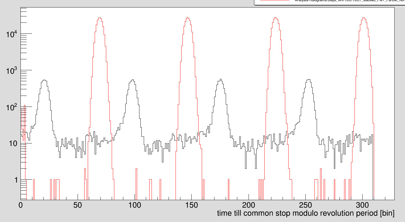
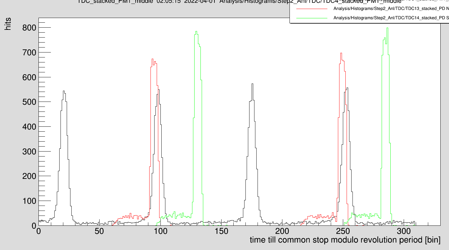
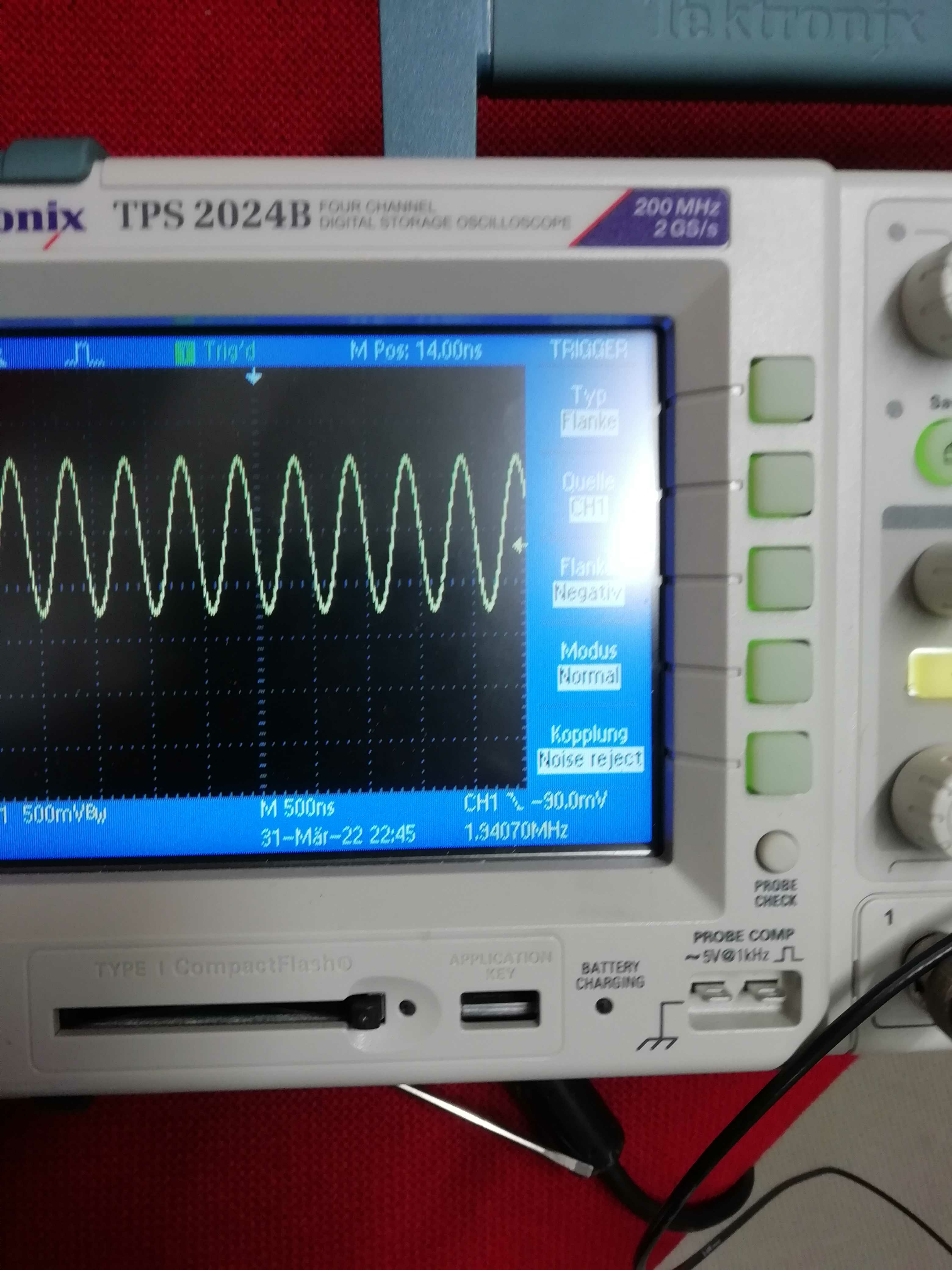
with bunched primary beam (bunching frequency 1.94070 MHz) we have strong PMT (mid) and particle detector signal. Time between both detectors was measured (in 3.3ns bins)

Particle Det ;  PMT (rising edge)
305 ; 256
227 ; 179
150 ; 102
73 ; 24


PD and PMT signal is second plot. Laser timing was not adjusted jet since it will change with Th beam. |
| Attachment 1: Particle-PMT_Mid.png
|
|
| Attachment 2: PMT-PD.png
|
|
| Attachment 3: IMG_20220331_235846.jpg
|
|
|
119
|
Thu Apr 7 00:36:36 2022 |
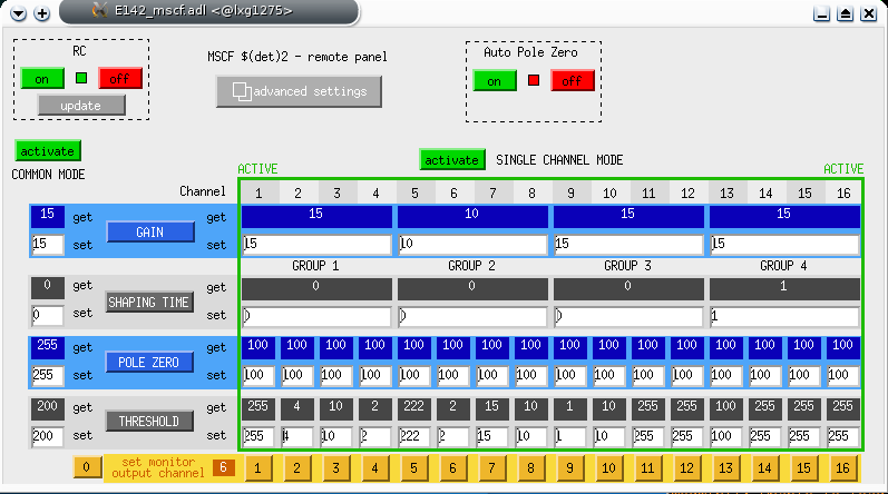
Uwe | DAQ | Threshholds and shaping Mesytec for ADC |
|
| Attachment 1: snapshot3.png
|
|
|
209
|
Mon Apr 11 12:50:22 2022 |
Kristian | Accelerator | Th lifetime |
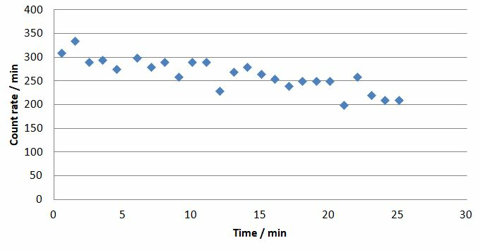
We used the counter to measure the lifetime. During the 30 min scan time dropped only slowly.

During a longer break, e.g., when the laser flash lamps are changed, one could take data over a longer time. |
| Attachment 1: ThLifetime.JPG
|
|
|
Draft
|
Sat Apr 2 01:02:39 2022 |
Carsten | | Test measurements with two DAQs |
We do two measurements:

One measurement using the |
|
67
|
Sat Apr 2 17:47:16 2022 |
Ken Ueberholz | | Telefon, Gästehaus |
My guesthouse phone number: 06159-71-2957 |
|
146
|
Fri Apr 8 01:18:51 2022 |
Ken Ueberholz | DAQ | TODO: DAQ improvements |
For somebody who knows the DAQ1 code: Go4 resets the histograms with each laser step. Can there be additional histograms where the data gets accumulated?

And possibly a histogram where important detectors are plotted against the laser steps? The read back wavelength of the wavemeter is not very precise. |
|
24
|
Mon Mar 21 10:46:18 2022 |
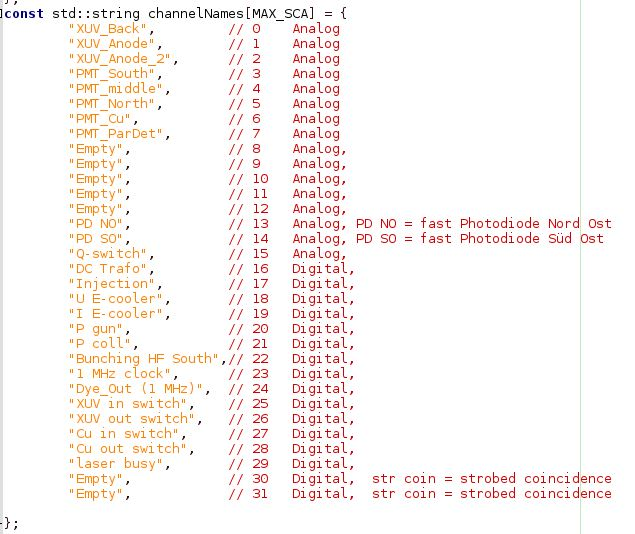
Rodolfo | DAQ | TDC & Scaler description channels |
For the First Vuprom we have the following channel configuration (Stand:21.03.2021).
Please note 1.
- CH 0 to CH 15 are the TDC channels
- CH 16 to CH 31 are the SCALER channels
Please note 2.
This is still under construction |
| Attachment 1: Screenshot_TLdaInputDescription_21-03-2022.JPG
|
|
|
93
|
Tue Apr 5 09:39:01 2022 |
Danyal & Yuri | Accelerator | Strahl ist wieder im ESR - Schlitz war reingefahren |
Der Strahl ist wieder im ESR!
Angeblich war einen Schlitz, oder sogar 2, reingefahren worden.
Es könnte entweder der GEEXDR11S und/oder den GEEXDR1AS  gewesen sein.

Wir haben jetzt folgende Parameter:

SIS Injektionsenergie = 537.5 MeV/u  (haben wir nicht geändert)
Chopper window 70 us (nicht geändert)

Wir haben jetzt etwa 1.2e9 Ionen pro Injektion im ESR |
|
31
|
Wed Mar 23 16:58:33 2022 |
V. Hannen | Detectors | Status copper mirror and XUV detectors |
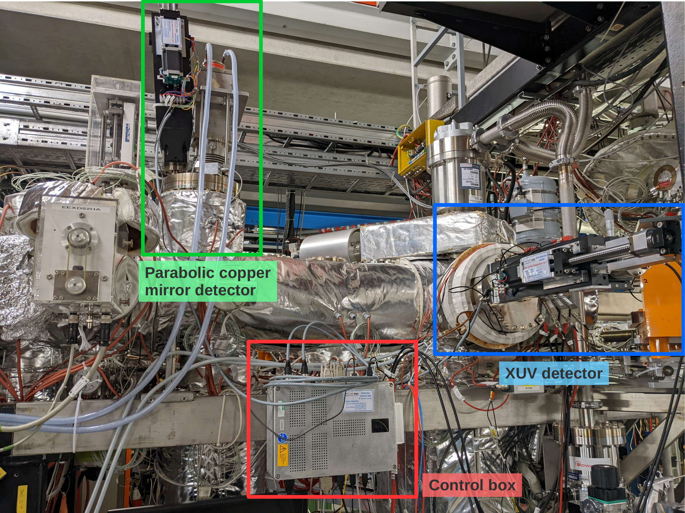
Over the past days, the parabolic copper mirror and XUV detectors haven been prepared and tested for the upcoming beamtime (see first attached photo for an overview of the detectors).
The positioning of the mirror and the cathode of the two detectors in their central positions in the beampipe have been adjusted. To reach this central position, the XUV cathode has to be moved 147 mm out of the parking position, while the parabolic mirror has to be moved by 173 mm. While the parabolic mirror will most probably always be driven the full pathlength to make maximum use of the Doppler shift of the emitted photons, the cathode will be placed somewhere in between parking and beam position to minimize background while still having a good detection efficiency.
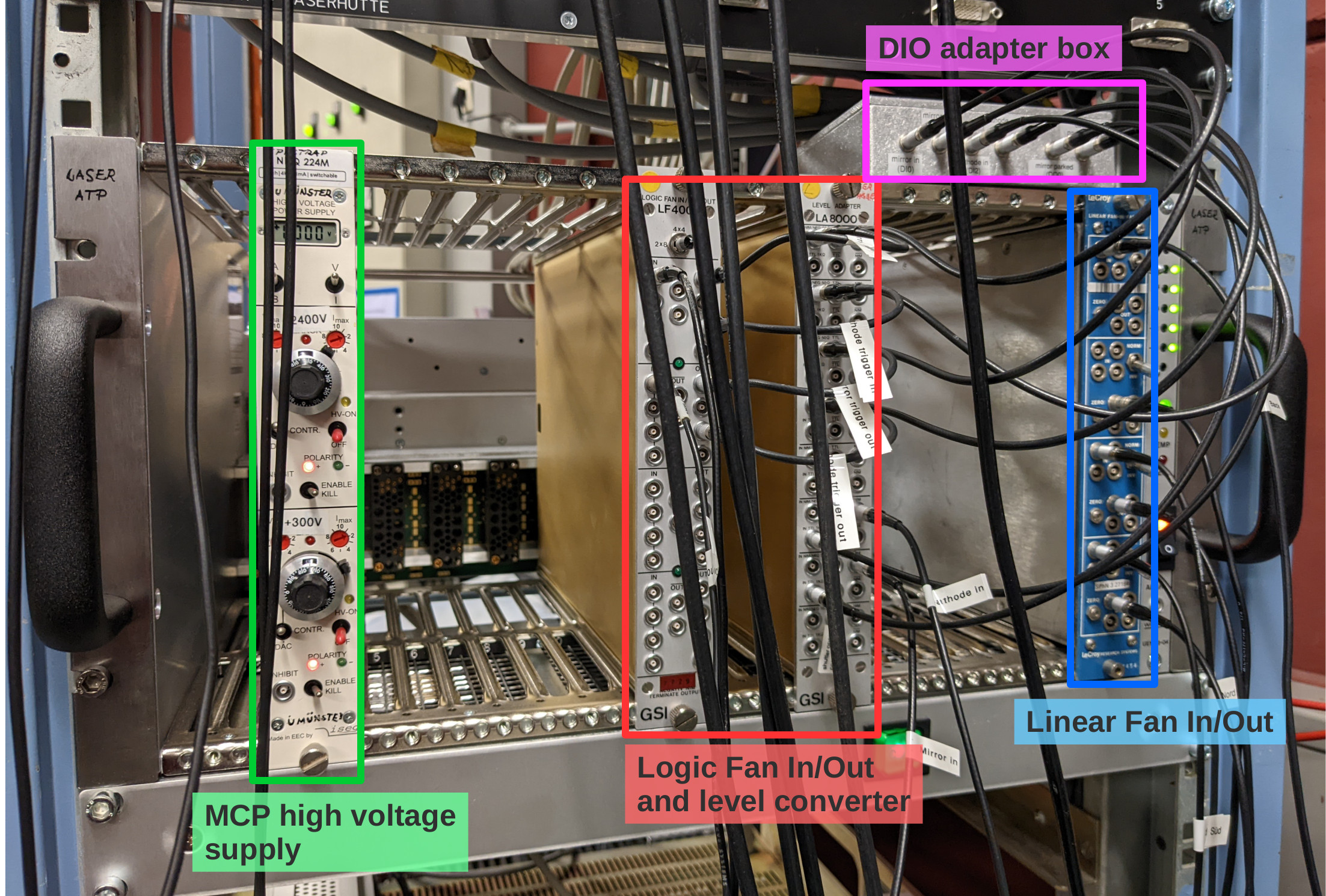
The MCP of the XUV detector is supplied with high voltage using an iseg 2 channel HV supply located in a NIM crate in the laser lab (see second photo). The required voltages are: +2400 V for the anode (upper channel) and +300 V for the MCP front (bottom channel).
The PMT of the copper mirror detector is supplied with HV by the same module as the PMTs on the new mirror chamber and has to be operated at a voltage of -1300 V.
The analog signals of both detectors are amplified by a factor 100 inside the ESR and patched through to the "Messhütte". For the MCP, the anode and MCP back signals are used (the MCP front signal is weak and noisy and doesn't give additional information). The MCP back signal has a positive polarity and is inverted in a linear Fan In/Out module in the NIM crate in the laser lab prior to discrimination.
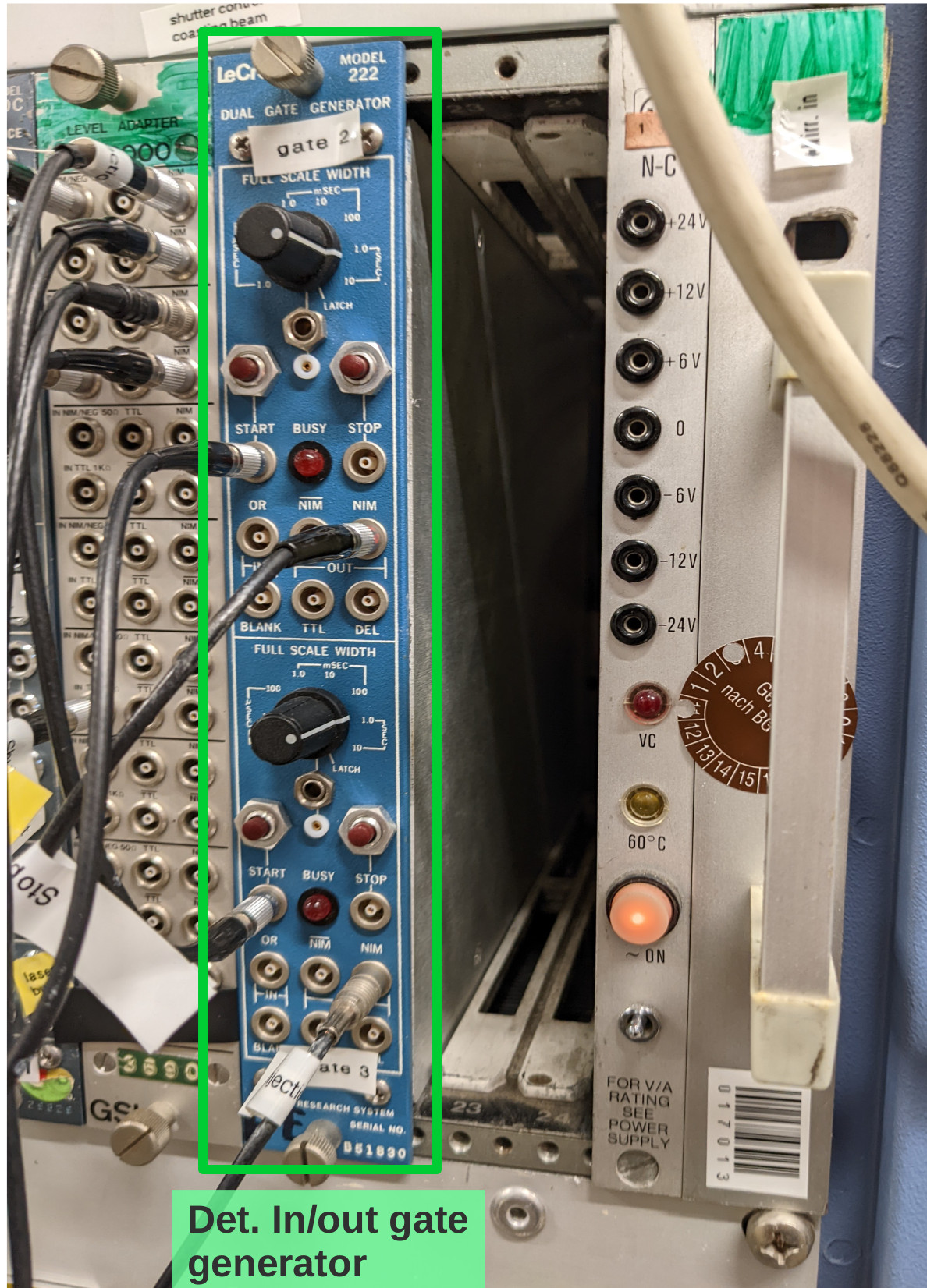
To trigger the movement of the copper mirror and the cathode from their respective parking positions to the measuring positions and back during each filling cycle of the ESR, two signals labeled "trigger in" and "trigger out" need to be provided from the ESR. These signals have to be connected to the "START" inputs of the gate generator in the Messhütte shown in the third photo. The upper channel processes the "trigger out" signal, the lower channel the "trigger in" signal. From the gate generator the signals are patched to the laser lab, where they are multiplied and converted to TTL in the NIM crate shown in photo 2, and transfered to the detector control box using the adapter on top of the crate. Automatically moving the detectors in and out only works when the control software is running and the "Automation" radio buttons are checked (see software manual in Elog entry 30).
Still to be done:
- connecting the analog signals to CFDs in the Messhütte and subsequently to the TDC inputs
- determining dark count rates when all pressure gauges in the straight section on the detector side of the ESR are switched off
- check influence of new ion getter pump on the XUV detector dark count rate.
Should we not be around and help is needed with these detectors call:
Volker Hannen - 0176 50129187
Ken Ueberholz - 01578 5999489 |
| Attachment 1: det-overview.jpg
|
|
| Attachment 2: laserlab-crate.jpg
|
|
| Attachment 3: trigger-module.jpg
|
|
|
202
|
Sun Apr 10 15:29:53 2022 |
Rodolfo | Laser | Status - Laser system |
We have checked the laser system.
- The pump laser has ~ 23Mio shots. The total output energy has dropped to about 475 mJ. Maybe it is time to install new fresh flashlamps. In case the accelerator is going to have any mantainance tomorrow (Monday) then we can take the oportunity to exchange the flashlaps.
- The dye laser is pumped with 470 mJ (angle of lambda/2 plate = 112°).
- The energy after the second harmonic is 11,3 mJ @ 646 nm. We are using the Sarper's calibration table (635 nm - 646 nm) |
|
51
|
Fri Apr 1 11:00:41 2022 |
Rui-Jiu Chen | DAQ | Start NTCAP |
Start taking data with NTCAP.
Carrier Frequency: 245MHz
IQ rate:5 MSamples/s
Reference level -0 dBm.
RF - Attenuation:40 dB
IF attenuation: 19.9288 dB

Date Files:
Samples/Record:2^18=262144
Records/File:2^12=4096
Masterpath: p:\E142\iq\IQ_2022-03-30_09-39-26
p:\E142\sc\SC_2022-03-30_09-39-26

Free space: o diver: 34.9TB. p driver: 34.8TB. |
|
98
|
Tue Apr 5 13:28:06 2022 |
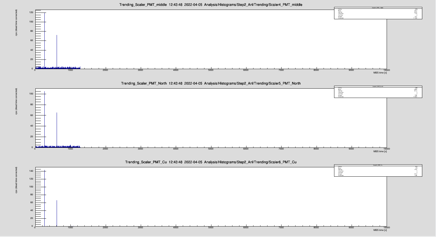
Kristian | DAQ | Spikes in PMT signal |
Occasionally, we noticed a spike in the PMT signal. No ions in the ring and at PMT Cu was not even supplied with HV. Has to be some electronic pickup |
| Attachment 1: spike.png
|
|
|
171
|
Fri Apr 8 22:26:44 2022 |
Patrick | DAQ | Spike in all detectors |
In the previous shift, there was a spike in all detectors in the same scan step. Apparently, this was NOT a resonance since in the next step it appeared again but at a different wavelength.
The current hypothesis is, that this is a disruption signal from one of the machines. |
|
168
|
Fri Apr 8 15:45:24 2022 |
YL | | Spectrum manipulation 5 |
See attached |
| Attachment 1: IMG_3027.JPG
|

|
|
142
|
Thu Apr 7 16:50:22 2022 |
Konstantin | Calibration | Spacial laser-ion overlap |
Laser-ion-beam overlap was achieved after measuring the ion beam positions (compare Entry 83).
Screenshots are comprised in the following table.
|
|
167
|
Fri Apr 8 15:42:20 2022 |
Yuri | Accelerator | Slits in the TE line |
At around 15:00, The slits in the TE line were changed to :
TE4DS5HL -12 mm -> -20 mm
TE5DSAH 0 mm -> +15 mm |