| ID |
Date |
Author |
Category |
Subject |
|
11
|
Thu Mar 3 13:50:45 2022 |
Rodolfo | Laser | Dye cell cracket |
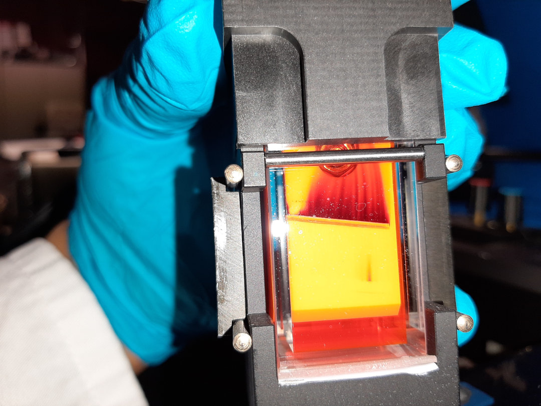
| The "20 mm" dye cell used for the Oscillator and Pramplifier got damage. I supposed it was produced by the pump beam hitting on a very "old" dye solution (DCM / Ethanol, concentration 0,3 g/l). The solution in the dye reservoir was more 12 months old. |
| Attachment 1: Cobra_Farbstoffzelle_08-02-2022.jpg
|
|
|
179
|
Sat Apr 9 05:00:11 2022 |
Carsten | General | Draft Docs and cheat sheet |
Please check the attached files,

and correct or enhance them.

Print out a copy |
| Attachment 1: e142_daq2_cabling.ods
|
| Attachment 2: Documentation_for_beamtime_2022_.doc
|
|
80
|
Sun Apr 3 13:05:08 2022 |
Carsten | Laser | Distance of Partilce detecotrs wr.t. to electron cooler |
As of Yuris post in the elog the positions (Info from H. Weick):

The postion of the particle counter behind the cooler is 21.6 m behind the middle of the cooler.
This correspond to 21.6m /108,4m = 1 / 5.02 of a full revolution (please check the present revolution frequency, i.e. for 2MHz, i.e. 500ns we have the signal approx 100ns after the ion is in the middle of the cooler).
If the detecot Nord would be used for bunch timing (only planned if detctor south is defect) the distance is half a ring + 21.4m, beind the center of the cooler, i.e. (54.2m+21.6m)/108.4m ~ 0.7 |
|
74
|
Sun Apr 3 10:28:25 2022 |
Yuri (Helmut Weick) | Accelerator | Distance cooler - detector |
Calculation from Helmut Weick
Distance e-cooler to particle detectors chamber:
“This is half of ESR plus distance target - detector. This even is on the web page”
54.28 m + 21.64 m |
|
8
|
Thu Oct 14 10:21:46 2021 |
Rodolfo | Detectors | Dismounting Cu-Mirror |
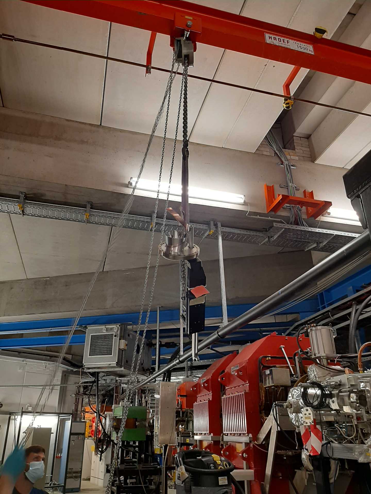
We have dismounted the parabolic Cu-Mirror at ESR on 13.10.2021 |
| Attachment 1: AusbauCuSpiegel_2021.jpg
|
|
|
32
|
Thu Mar 24 13:27:47 2022 |
Rodolfo | DAQ | Disk space - LXG1297 |
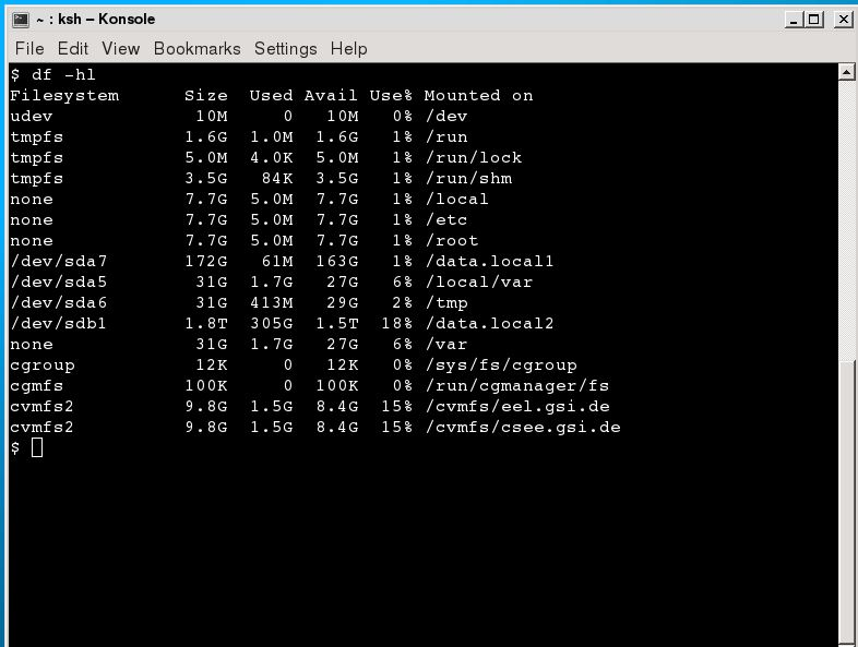
In our Linux computer (LXG1297: Laser spectroscopy) we have a Drive with 1.8 TB total disk space. 300 GB are at the moment in use, but I can clean this.
This computer is located in the "Atomphysik Messhütte". |
| Attachment 1: DiskSpace_lxg1297.JPG
|
|
|
101
|
Tue Apr 5 20:16:13 2022 |
Rodolfo | Laser | Discriminator for HF reference signal |
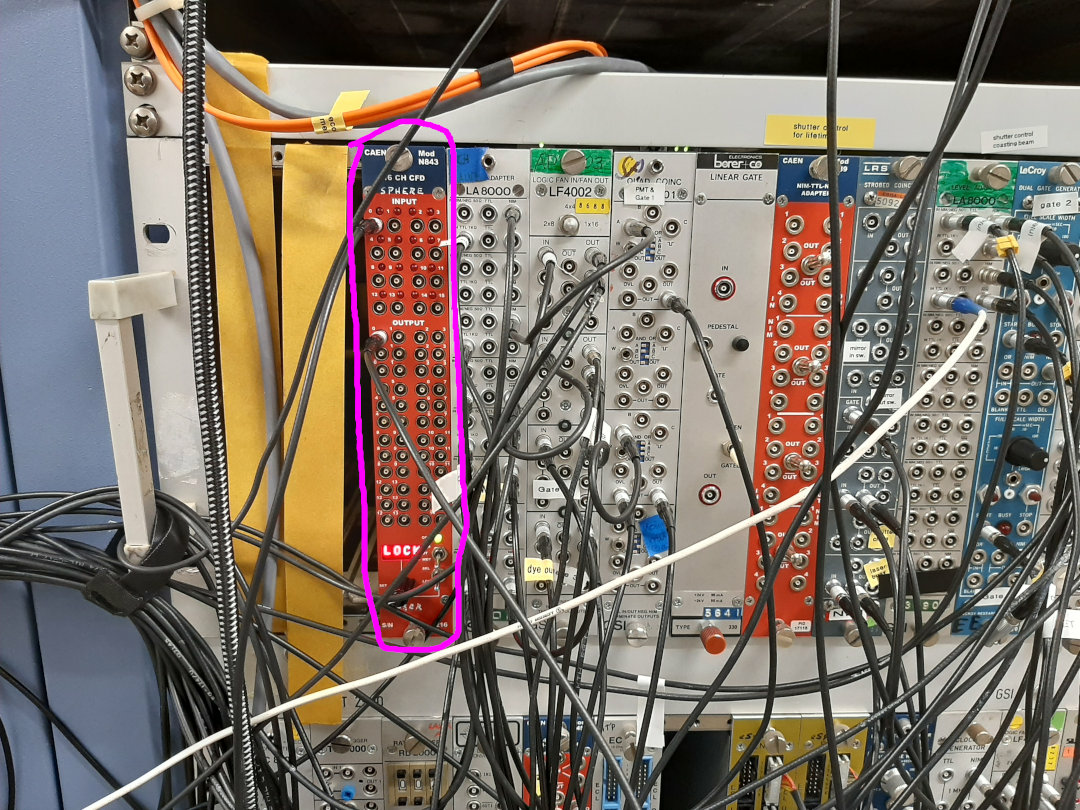
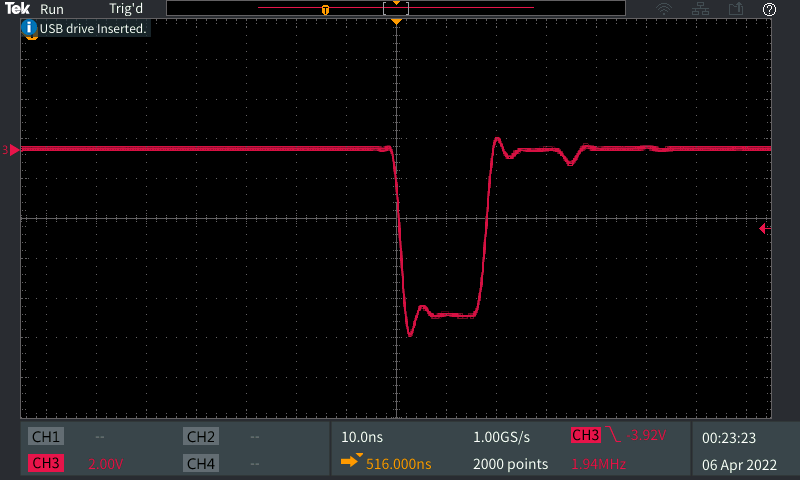
For the laser trigger we need to generate a few ns NIM-puls from the HF reference signal. Therefore we (Wilfried, Konstantin and me) have changed the constant fraction descriminator (CFD) to generate this kind of pulse.
- We are using now the module N843 from CAEN, see picture below. With this we could now produce ~20 ns long pulse.
- This signal is also used as STOP trigger for the VUPROMs |
| Attachment 1: CFD_für_HFSignal.jpg
|
|
| Attachment 2: Disc_HFSignal_05-04-2022.PNG
|
|
|
75
|
Sun Apr 3 10:35:20 2022 |
Yuri (Sergey) | Accelerator | Dipole correction |
The ramp for moving the beam to the central orbit
To be inserted into manipulation, GE01MU1 (SC 5): 1.05969755 rad
This can be done only when one stays in the manipulation 5
Afterwards “Manipulieren” and not “An Geräte schicken” |
|
141
|
Thu Apr 7 16:45:10 2022 |
| Detectors | Detector distances |
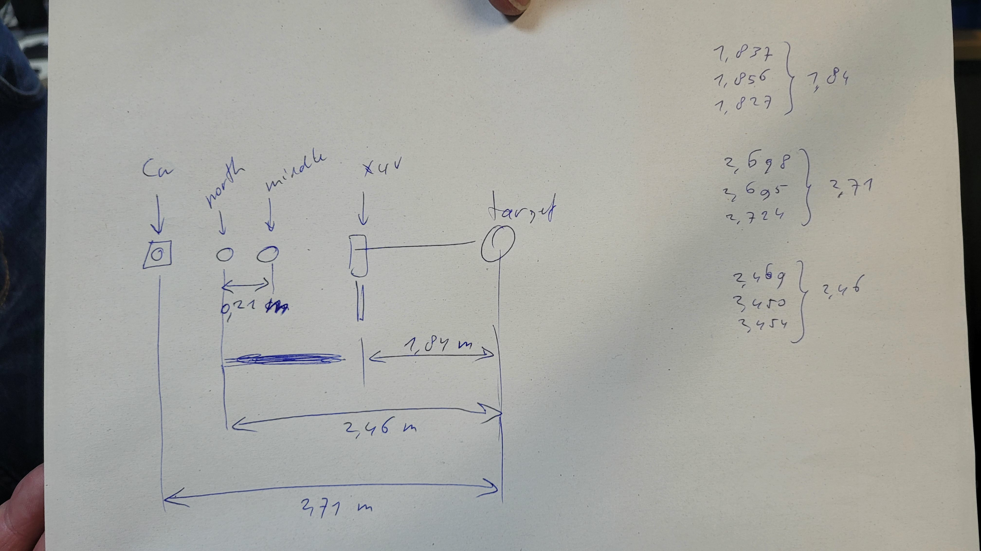
Relativ distances of the detector |
| Attachment 1: 20220407_164345.jpg
|
|
|
163
|
Fri Apr 8 14:14:28 2022 |
Kristian | DAQ | Delay of bunch RF |
The bunch HF is now fed through a delay to shift the stop trigger relative to the PMT signal. The delay generator is placed directly after the CFG and before splitting the signal for the two DAQs. The relative timing of both DAQs was not changed. |
|
133
|
Thu Apr 7 09:23:18 2022 |
Sebastian | DAQ | DAQ1 & DAQ2 - 1kHz and delayed cs removed |
Questionable 1kHz and delayed common stop signals has been removed.

These two cablings were for some previous tests. |
|
41
|
Thu Mar 31 13:28:17 2022 |
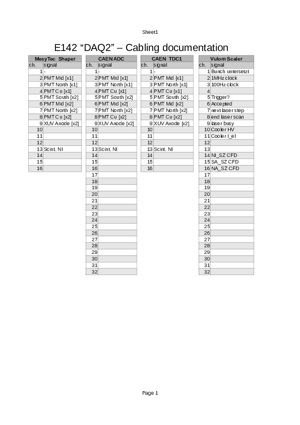
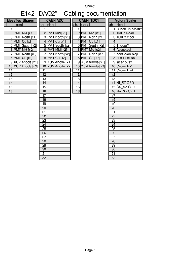
Jan Glorius | DAQ | DAQ-2 cabling docu |
newest version V2 - valid since Mo 04.April 2022 |
| Attachment 1: e142_daq2_cabling.pdf
|
|
| Attachment 2: e142_daq2_cabling_V2.pdf
|
|
| Attachment 3: e142_daq2_cabling_V2.ods
|
|
153
|
Fri Apr 8 08:40:06 2022 |
Sebastian | DAQ | DAQ improvement |
Concerning ID 146 a new histogram for accumulating data (no cleaning histograms) can be found under

Step2_Anl/TDC/TDC***_accumulated_*** |
|
172
|
Fri Apr 8 23:56:07 2022 |
Patrick | DAQ | DAQ improvement |
As requested in ID:146 and ID:147, the laserscan tab was improved:
- The laserscan tab shows each observable plotted against the predefined wavelength setpoints now.
- The Kobra set wavelength shows the actual setpoints now and not measured wavelengths.
Note: The bins of the laserscan histograms are defined in TLdaAnlProc.cxx, lines 140-142.
At the moment, the histograms are set up for scans in the range 320 - 325 nm and step sizes of 0.01 nm.
If the step size changes or scans that exceed this range are required, these parameters should be adjusted.
Remember to add or subtract half of the step size to your min. and max. wavelength to prevent binning artifacts.
Then of course, also only scan wavelengths which are multiples of your step size. |
|
122
|
Thu Apr 7 03:06:15 2022 |
Patrick | DAQ | DAQ file sizes |
The file sizes of DAQ1 (229Thor) and DAQ2 (229Th, "Carstens DAQ") are different.
During 20min of laser scanning DAQ1 saves 4 files while DAQ2 saves 2 files which was 3.3 GB and 2 GB, respecively.
The file sizes of DAQ2 should always be greater than those of DAQ1, because of extra ADC data!
The problem seems to be solved after the recabling ID: 125. |
|
140
|
Thu Apr 7 15:18:25 2022 |
Danyal & Sebastian | DAQ | DAQ channels |
We checked again the cables for both DAQs
(on Carsten's kind request)


Channels for both DAQs are:

0 XUV-Back
1 XUV-Anode
2 XUV-Anode-delayed
3 PMT-South (new PMT, new threshold)
4 PMT-Middle
5 PMT-North
6 PMT-Cu
7 Part-det-south
8 Part-det-north
9 -
10 -
11 -
12 -
13 PD-NO
14 PD-SO
15 Q-switch |
|
34
|
Thu Mar 24 17:10:33 2022 |
Carsten | DAQ | DAQ / MBS VUPROM TDC buffer errors |
VUPROM TDC buffer errors potentially due to long TDC common Stop gate (>1ms from div 200).
Signal piped through coinc. unit gicv es shorter sginal (~200ns). This signal used as common stop seems to have cured the TDC buffer errors.. |
|
72
|
Sat Apr 2 23:16:55 2022 |
Carsten | | Cu mirror and CsI moved in and out of the ring |
Ken tested the Cu-mirror and CsI disk Detector. They move without a problem and don't scrape the ion beam. |
|
125
|
Thu Apr 7 04:10:18 2022 |
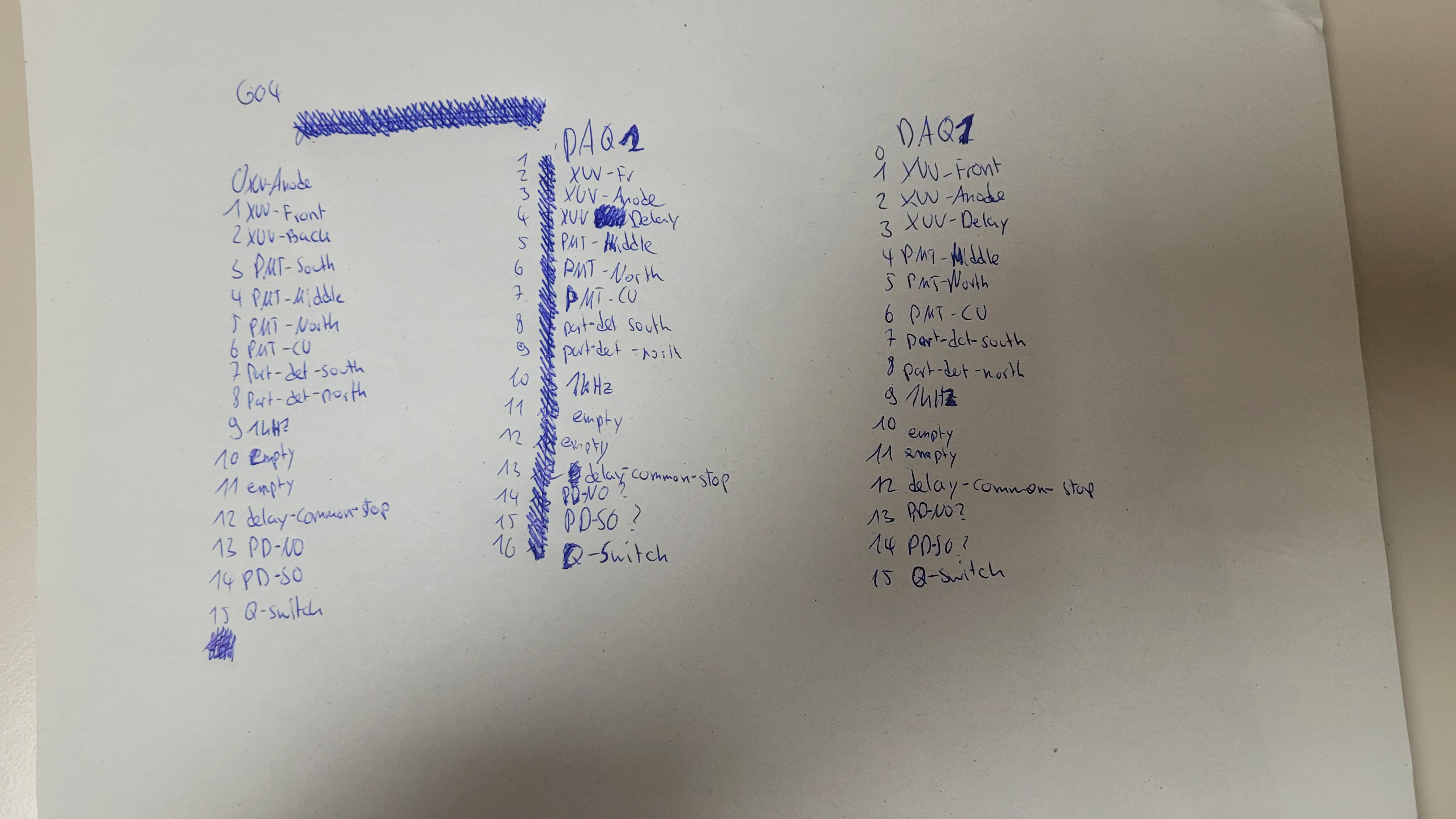
Ken Ueberholz | DAQ | Corrected cabling DAQ 2 |
A lot of cables were wrongly or not
connected to the DAQ 2.

Channels are now for both DAQ:
0 XUV-Back
1 XUV-Anode
2 XUV-Anode-delayed
3 PMT-South
4 PMT-Middle
5 PMT-North
6 PMT-Cu
7 Part-det-south
8 Part-det-north
9 1kHz
10 -
11 -
12 Delay-common-stop
13 PD-NO
14 PD-SO
15 Q-switch

All data taken by the DAQ2 has to be
considered as faulty up to now.

Carsten was furious. |
| Attachment 1: 20220407_043337.jpg
|
|
|
91
|
Mon Apr 4 19:05:57 2022 |
Carsten | DAQ | Cooler Frequency Signals Ion current not connected until now |
Up to now the signals for
Ion Current
Cooler elctron current
Cooler voltage (frequency)
were not connected to the DAQs et al.

Cables in the "rded corner", i.e. where their original soruce is were not connected !!! |