| ID |
Date |
Author |
Category |
Subject |
|
1
|
Fri Apr 25 15:45:39 2025 |
Jan Glorius | DAQ | DR DAQ - MBS & Go4 |
The DR DAQ is located in AP Messhuette, here is the basic info.
MBS
node: x86l-151 (NUC)
user: litv-exp
screen session: DRdaq
MBS location: /esr/usr/litv-exp/MVLC/2025_DR_ESR (use symbolic link: /esr/usr/litv-exp/currentDAQ)
enter DAQ session with: /esr/usr/litv-exp/MVLC/2025_DR_ESR/daq.sh or ./daq.sh in the dir
kill and restart DAQ with: /esr/usr/litv-exp/MVLC/2025_DR_ESR/daqstart.sh or ./daqstart.sh in the dir
Recorded data:
WR timestamp
8 trigger types available
32 scaler channels available
Go4
PC: x86l-202 (but any with go4-login should work)
user: litv-exp (or any other)
MBS location: /esr/usr/litv-exp/go4/2025_ESR_DR_v0
path on lxg-machines: /lynx/Lynx/esr/usr/litv-exp/go4/2025_ESR_DR_v0
VNC server on x86l-202 can be used for Go4 or mvme if needed. Simply use the tigervnc icon "VNC x86l-202" on lxg-desktops of litv-exp.
RFIO & ESR-NAS
The data is stored via an rfio server (atprfio.gsi.de) on the ESR-NAS. The local folder on the NAS is /mnt/raw.data/2025_DRALS_Brandau/
The entire /mn/raw_data folder can be mounted to /esr/usr/litv-exp/exp_mnt/data.ESR on any x86l-XXX machine by using the alias "mountESR" or "sshfs -o directport=7777 atprfio.gsi.de:/mnt/raw.data /esr/usr/litv-exp/exp_mnt/data.ESR". |
|
Draft
|
Wed Apr 30 19:59:18 2025 |
Carsten | DAQ | DR_DAQ |
      	enum{TRIG_INJECTION=1,
	    TRIG_NEWRAMP=2,
	    TRIG_NEWVOLTAGE=3,
	    TRIG_VOLTAGE_SUB1=4,
	    TRIG_VOLTAGE_SUB2=5,
	    TRIG_VOLTAGE_SUB3=6,
	    TRIG_VOLTAGE_SUB4=7,
//	    TRIG_VOLTAGE_SUB5=8,
//	    TRIG_VOLTAGE_SUB6=9,
//	    TRIG_VOLTAGE_SUB7=10,
	    TRIG_ENDOFRAMP=8, //presently 20 Hz MVLC
	};

        double  f_ParticleDetSA_sc; // 1: Particle Counter SA -*
        double  f_ParticleDetNA_sc; // 2: Particle Counter NA -*
		double  f_ParticleDetNI_sc; // 3: Particle Counter NI -*
		double  f_Injection_sc; // 4: Injection in Scaler -*
		double  f_NewRamp_sc; // 5: New Ramp in Sc -*
		double  f_NewStep_sc; // 6: New Step in Sc -*
		double  f_ICur_sc; // 7: Ion Current in Sc -*
		double  f_tm_sc; // 8: 1MHz  -*
		double  f_dummy09_sc; // 9:
		double  f_HVDivider_sc; // 10: HV drifttubes, measured with divider -*
		double  f_dummy11_sc; // 11:
		double  f_ECurrent_sc; // 12: Electron Current Cooler -*
		double  f_CoolHV_sc;// 13: Voltage of Electron Cooler -*
		double  f_dummy14_sc; // 14:
		double  f_dummy15_sc; // 15:
		double  f_tm100Hz_sc;// 16: 100 Hz from MVLC IO
        double  f_dummy17_sc; // 17:
        double  f_dummy18_sc; // 18:
        double  f_dummy19_sc; // 26:
        double  f_dummy20_sc; // 27:
        double  f_dummy21_sc; // 28:
        double  f_dummy22_sc; // 29:
        double  f_dummy23_sc; // 30:
        double  f_dummy24_sc; // 31:
        double  f_sub1_sc; // 25: Subtrigger 1 sc
        double  f_sub2_sc; // 26: Subtrigger 2 sc
        double  f_sub3_sc; // 27: Subtrigger 3 sc
        double  f_sub4_sc; // 28: Subtrigger 4 sc
        double  f_sub5_sc; // 29: Subtrigger 5 sc
        double  f_sub6_sc; // 30: Subtrigger 6 sc
        double  f_sub7_sc; // 31: Subtrigger 7 sc
double f_dummy32_sc; // 32: |
|
3
|
Mon May 5 11:29:28 2025 |
Rodolfo, Simon, Nils, Volker | Detectors | PMTs |
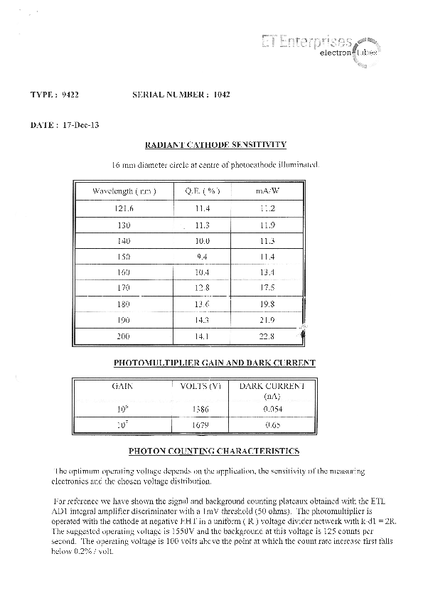
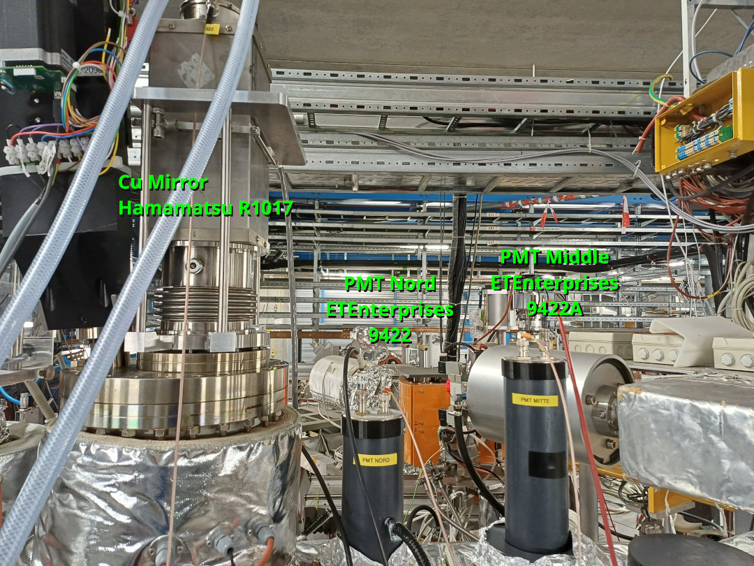
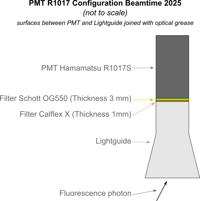
These are the PMTs installed at the optical detection region:
|
Label | Hersteller | Model | S.N. | Sensitivity | Operation voltage
| |
Cu-Mirror | Hamamatsu | R1017 (sel) | NA2313 | Infrared | -1300 V
| |
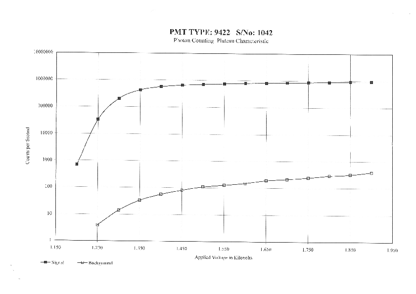
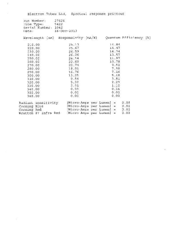
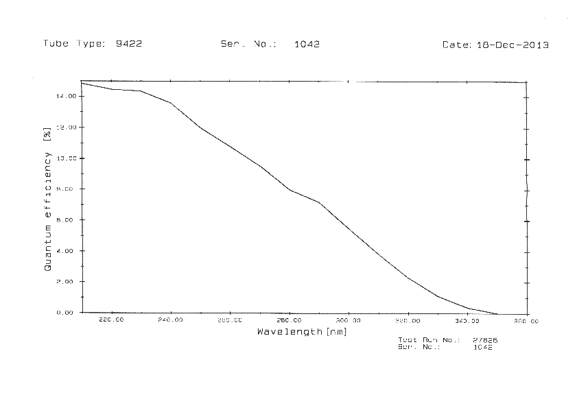
PMT Nord | ET Enterprises | 9422 | 1042 | UV | -1500 V
| |
PMT Middle | ET Enterprises | 9422A | 1001 | UV | -1700 V
|
|
| Attachment 1: SolarBlind_ET_9422_SN1042.pdf
|
|
| Attachment 2: ThornEmi_PMT9422A_SN1001_(1987).pdf
|
-0.png)
-1.png)
-2.png)
|
| Attachment 3: PMT_Arrangement_Libelle2025.jpg
|
|
| Attachment 4: PMT_R1017_Configuration_Beamtime2025.png
|
|
|
4
|
Mon May 5 16:26:07 2025 |
Carsten | DAQ | DR Computer Names and IPs |
Computers used for control of HV amplifiers and DR microcontrollers are
- main control (big Philips monitor): sadpc058.gsi.de - 140.181.98.68
- NUC in ESR (DAC and HV divider ADC) : sadpc.gsi.de - 140.181.80.66
- Digilent scope in ESR (requires Digilent software installed, no user required): atpdev015.gsi.de - 140.181.82.76
- Seuencer NUC in Messhuette : NN - 140.181.92.75
only user on these machines: dr_esr (ask for PW)
DR go4 /mbs is controlled on lxg3113 under user litv-exp
(Details in post 1), more details concerning directory of Go4 etc.yet to come. |
|
5
|
Mon May 5 21:13:29 2025 |
Rodolfo | Laser | Collimation of laser beam |
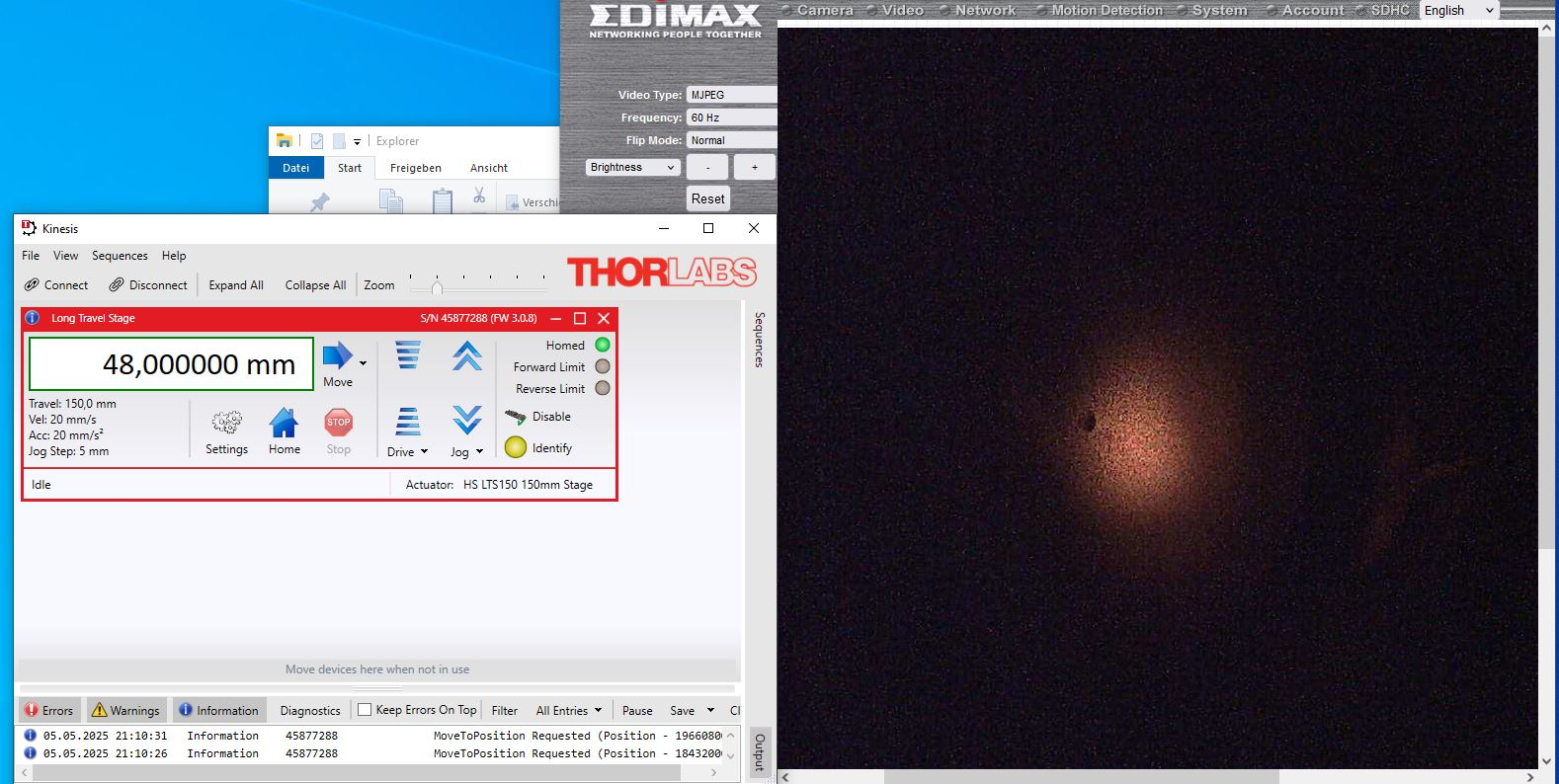
Here some parameters for the collimation of the laser beam
Periscope:
- Planconcav -500 mm
- Planconvex +1000 mm
Distance between both lenses: 504 mm.
Long Travel Stage @ 48,0 mm
The screnshot shows the laser spot at the screen "SO-Arc". |
| Attachment 1: Cobra593nm_Laserbeam_Collimation_2025-05-05.JPG
|
|
|
6
|
Tue May 6 15:35:12 2025 |
Rodolfo, Konstantin | Laser | MRC Settings |
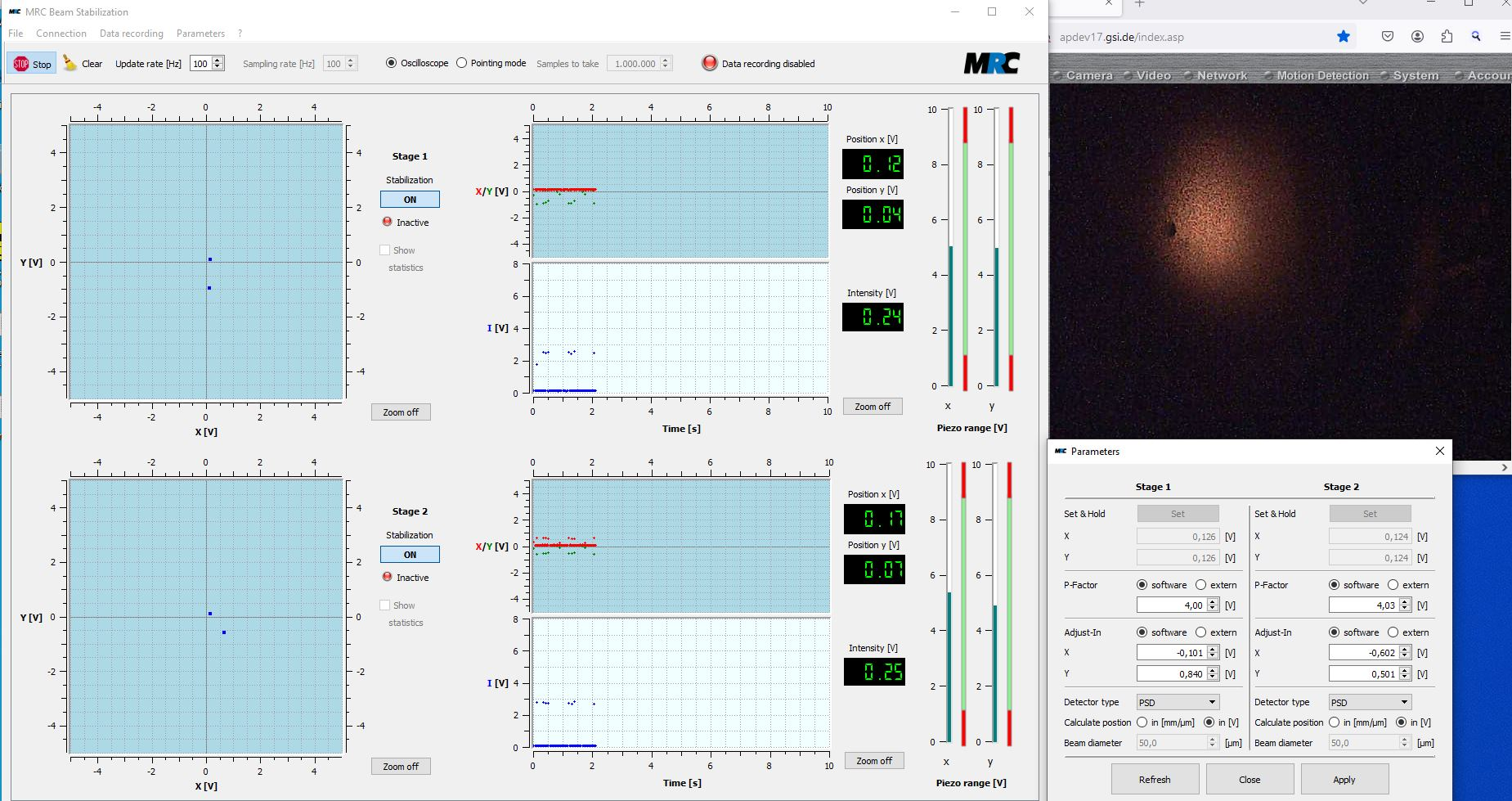
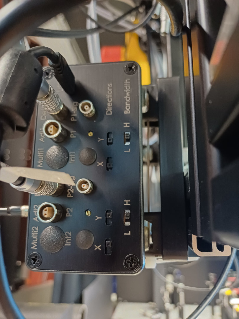
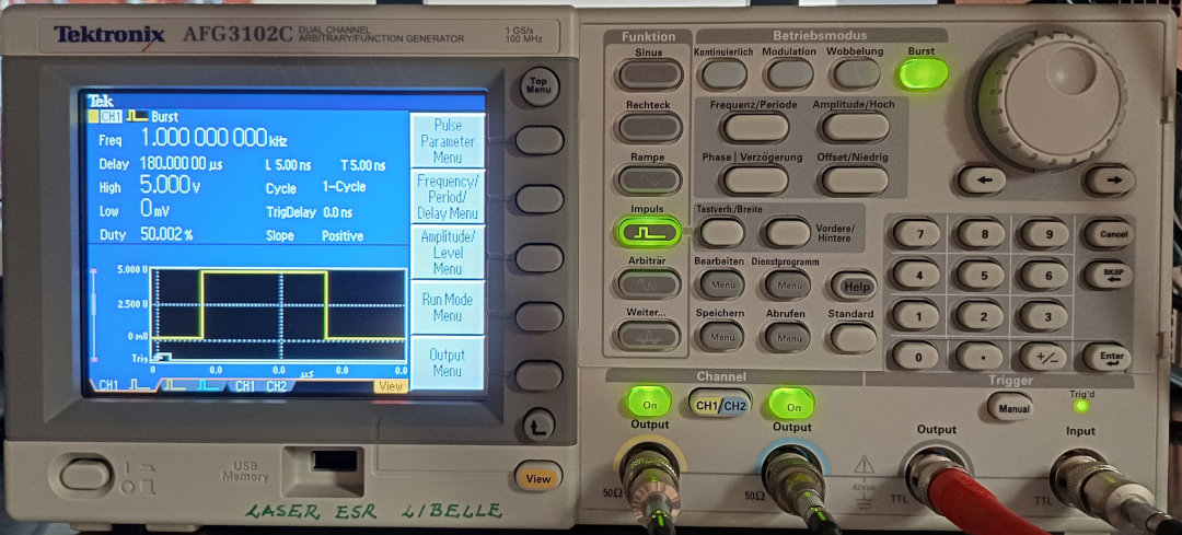
Following settings (P-Factor, Directions and Bandwidth) are used for the laser beam stabilization. Full energy (ca. 150 mJ @ 593 nm).
The triggers for the MRC are generated by AFG3102C. The settings (the same for both CH1 and CH2) are saved under "Abrufen / Setup2" |
| Attachment 1: MRC_Settings_Cobra593_VolleLeistung_2025-05-06.JPG
|
|
| Attachment 2: MRC_Controller_Settings_2025-05-06.jpg
|
|
| Attachment 3: AFG3202C_Settings.jpg
|
|
|
7
|
Wed May 7 14:02:58 2025 |
Konstantin | DAQ | DAQ Folder |
The folder of the data acquisition are:
Go4 (atplaser@lxg1297): ~/go4/drals
MBS (atplaser@r4l-41): ~/mbsrun/G038/DRALS |
|
8
|
Wed May 7 17:29:19 2025 |
Rodolfo, Simon | DAQ | Fast Photodiodes |
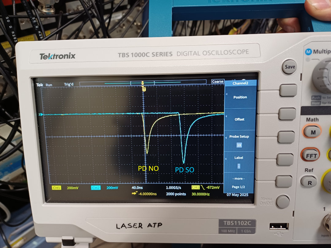
Signal for the fast photodiodes. The laser beam
- enters at the Nord-Ost (NO) Arc and
- leaves at the Süd-Ost (SO) Arc.
The photodiodes themself are located inside the laser towers. |
| Attachment 1: FastPD-Signals_Messhütte_2025-05-07.jpg
|
|
|
9
|
Wed May 7 20:31:52 2025 |
Carsten | DAQ | DRALS cabling (DR part) |
Green Corner, patch panel to ESR
All signals from/ to ESR TTL 5V.
Signals are GND decoupled with grey boxes! Don't use the signals directly.
[1] New Ramp (NR) / Meas Gate
[2] New Step (NS)
[3] End of Ramp (ER) / COOL
[4] to ESR: Start Measure Trigger
[5] to ESR: Laser Trigger (~ 30 Hz)
[6] MEAS0
[7] MEAS1
[8] VFC
Patch Panel "Green Corner" (DR) <-> "Blue Corner" (Laser)
Signals are neg NIM unless otherwise indicated
(i.e. the two signals from/to the DR Trigger side need to be TTL)
[11] to DR side: Laser Trigger (TTL) => to do => done
[12] from DR side Injection; signal comes from DR DAQ!!! => to do
[13] Meas Gate
[14] VFC
[15] to DR side: Part Det South (Cooler) => to do
[16] to DR side: Part Det North (Gas jet) => to do
[25] COOL
[26] MEAS0
[27] MEAS1
[28] New Step (NS)
[29] SubTrig 1
[30] SubTrig 2
[31] SubTrig 3
[32] SubTrig 4
NACOM 1 => Signals ar ORed as Master Readout Trigger and Counted in DRALS Scaler 9 to 16
[1] COOL => SC Ch9
[2] MEAS0 => SC Ch10
[3] MEAS1
[4] New Step (NS)
[5] SubTrig 1
[6] SubTrig 2
[7] SubTrig 3
[8] SubTrig 4 =Sc Ch16
The Measgate Signal (logic high when in measurement window) is ANDed with 100 kHz clock. The strobed signal is put in DRALS DAQ ( to do). |
|
10
|
Thu May 8 10:11:37 2025 |
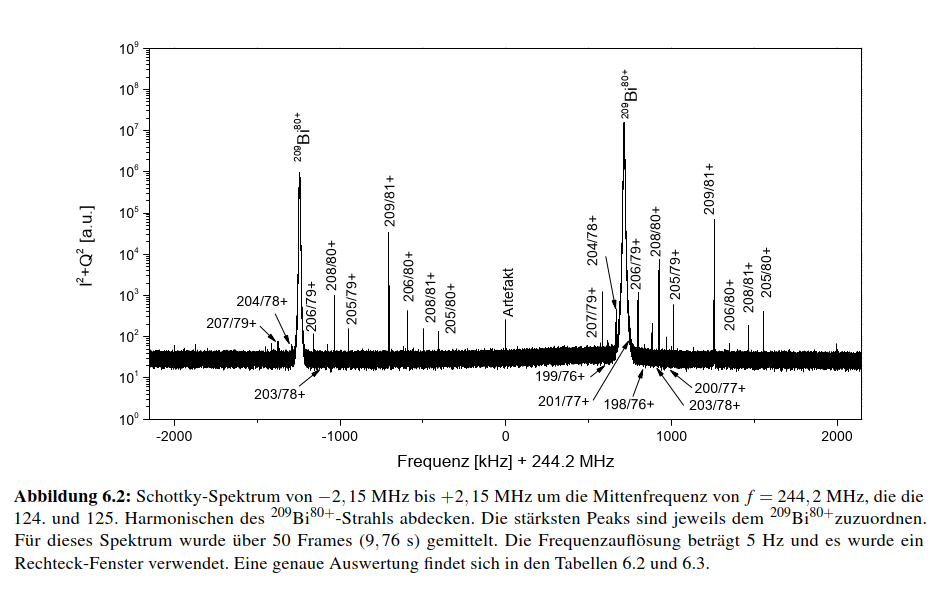
Carsten | General | Schottky spectrum ( 2 Harmonics) from the earlier 209Bi80+ Libelle run (thesis C. Trageser) |
|
| Attachment 1: Schottky_Libelle_on_209Bi80.png
|
|
|
11
|
Thu May 8 10:21:10 2025 |
Carsten | | Link to thesis of C. Trageser NTCAP/ Automated Schottky analysis of cooler voltage and space charge) |
The thesis of Christian might be helpful w.r.t. to energy calibration as it shows how to link Schottky frequency to ion energy (might be required since in DRALS the exact ion energy will be difficult to derive from voltage measurements only).
Cf., chapter 6 (thesis is in German)
Link: Thesis C. Trageser |
|
12
|
Thu May 8 13:33:13 2025 |
Rodolfo, Simon | Laser | Camera @ South-West Screen |
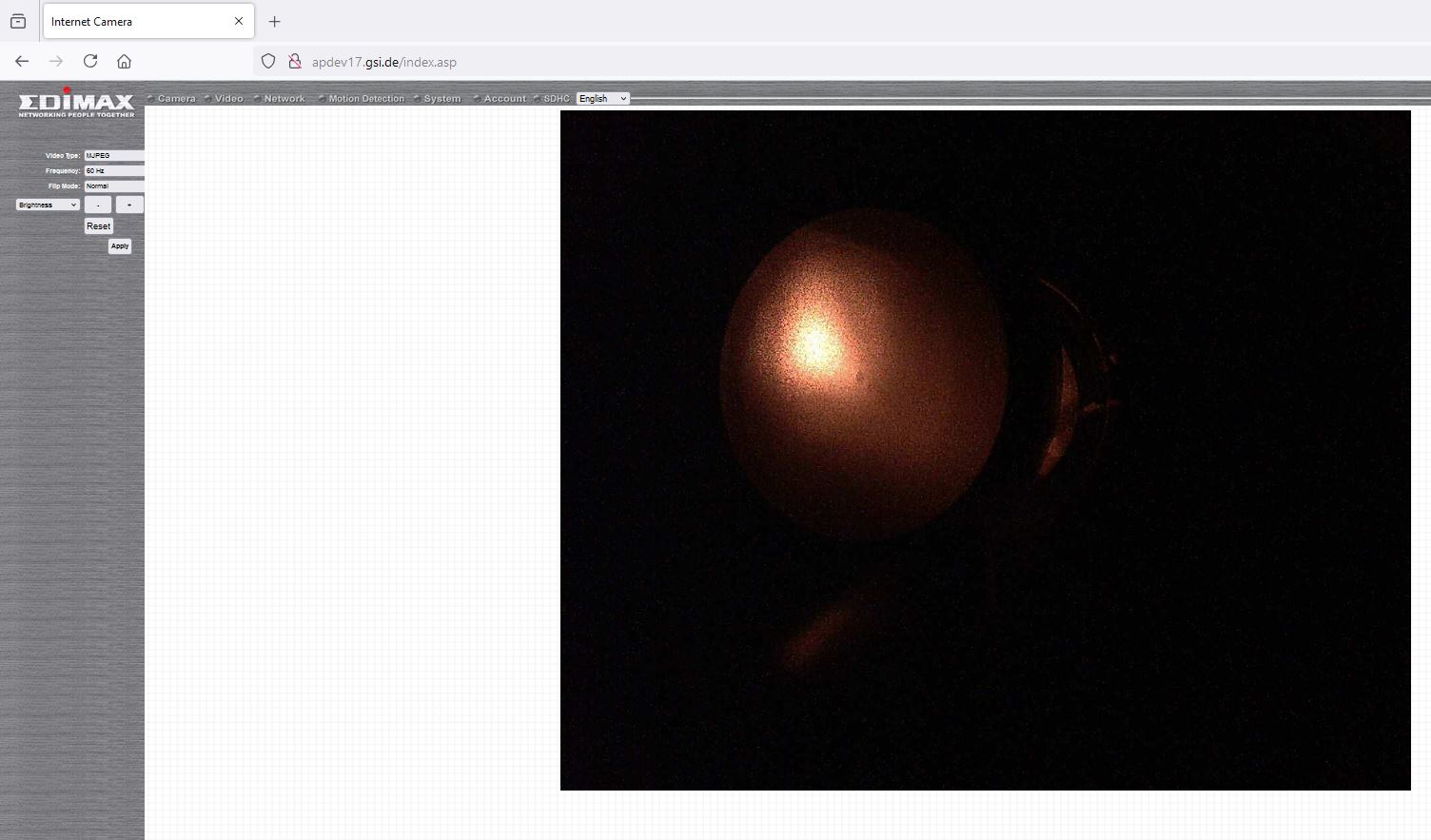
Network camera to monitor the position of the laser beam after the electron cooler.
apdev017.gsi.de
user: admin
password: 1234 |
| Attachment 1: Laserbeam@SW-Screen_2025-05-08.JPG
|
|
|
13
|
Thu May 8 17:23:51 2025 |
Shahab | General | Schottky TV |
setup Schottky TV:

connect to atppc030 using:

xfreerdp /u:atplaser /v:atppc030.gsi.de /w:1920 /h:1060

PW: given at label@LXG1297

this can be done also from the TCL computers

inside you open OBS Studio

then choose Video-Capture Device and both USB3 devices. |
|
14
|
Thu May 8 19:35:18 2025 |
Simon | | PMT count rates |
I tested the PMTs and tried to reduce the background signal as far as possible.
|
PMT | voltage (V) | count rate (Hz)
| |
Mid | 1700 | 1200
| |
North | 1500 | 900
| |
Cu | 1300 | 1400
|
PMT Mid count rate strongly fluctuates.
Turning the light on in the ESR has no influence on Mid and North but increases the rate for Cu by 200Hz. |
|
15
|
Thu May 8 22:50:37 2025 |
Carsten | DAQ | Preliminary Timing Settings |
Tentatively:
DAC:
Meas Gate: 8000 ms (8000000 us)
Cool Time: 16800 us
Meas0,1: 16800 us
Ramp Time: 3000 us
SubTrigger (us):
1: 5500
2: 2000
3: 2200
4: 2400
5: 200 (not wired)
6: 200 (not wired)
7: 200 (not wired)
These values together with 30 Hz produce nice Timer spectrum with separated peaks. |
|
16
|
Thu May 8 23:36:19 2025 |
Konstantin | DAQ | Fileserver |
To save files, the rfio-server must be started on lxg1297 in the folder /data.local2/BiDrals/. The file structure is
/data.local2/BiDrals/208Bi_XXX.lmd
where XXX is the current file number. To connect the mbs client to the file server, run the command
@connectdisk
on mbs. A file is opened and closed by running commands
@openfile
@closefile
respectively. To test whether a file is opened run
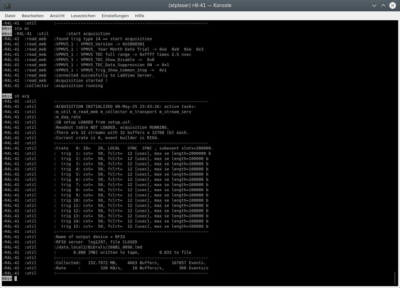
show acquisition
In the last rows of the output you will find the connection details and the status of the output file (see attachement). The attached screenshot displays that the RFIO server is connected and the file /data.local2/BiDrals/208Bi_090.lmd has been closed. |
| Attachment 1: MBS_SshowAcq.png
|
|
|
17
|
Fri May 9 00:56:07 2025 |
Konstantin | DAQ | First Files |
| Files 91 + 92 were recorded with the Trigger logic as explained in ID 15. The laser was scanned from 593 to 592 in 101 steps. 100 laser steps were accumulated at each step. Bunching HF was synthesized by an AFG with a frequency of 1.787327MHZ and divided by 89 |
|
18
|
Fri May 9 14:21:18 2025 |
Rodolfo | Accelerator | T-Scrapers |
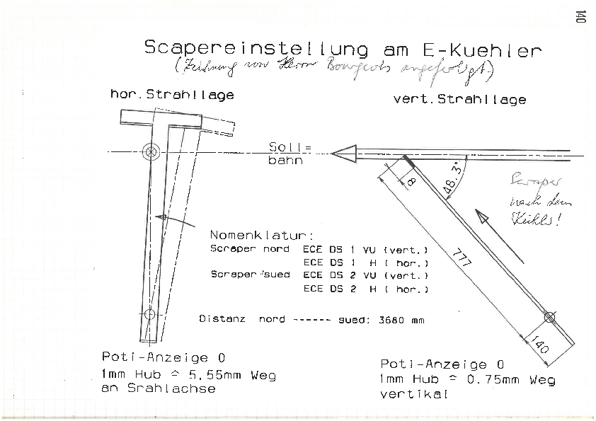
Information about the T-Scrapers at the ESR Electron Cooler. The width of the scraper is approx. 9 mm.
There was some issue about the Scraper GECEDS2VU. Herr Boywitt solved this issue and shortly communicated the procedure about how to move it.
Nils and me talked today with Sergey. He mentioned to go to position "-5 mm". Herr Boywitt wrote "-50", see below.
Mail vom 10.04.2025 um 13:26 Uhr.
Hallo alle,
wir haben den ESR Scraper instand gesetzt.
Am mittenkontakt hatte sich eine Verbindung gelöst, weiterhin haben wir den Mittenkontaktschalter neu justiert.
Der Antrieb sollte , um den Mittenkontaktschalter auszulösen, von der Endlage außen auf die Position -50 gefahren werden.
Viele Grüße
Robert |
| Attachment 1: Scrapereinstellung_am_ESR.pdf
|
|
|
19
|
Fri May 9 17:47:07 2025 |
Konstantin | DAQ | HV Divider |
| The HV voltage applied at the high-voltage platform of the electron cooler can be observed at HV-divider. |
|
20
|
Fri May 9 18:34:08 2025 |
Konstantin | DAQ | Important diagnoses of analysis parameters |
The filling of some histograms in the go4 analysis framework is controlled by the SetParameters.C and SetConditions.C files.
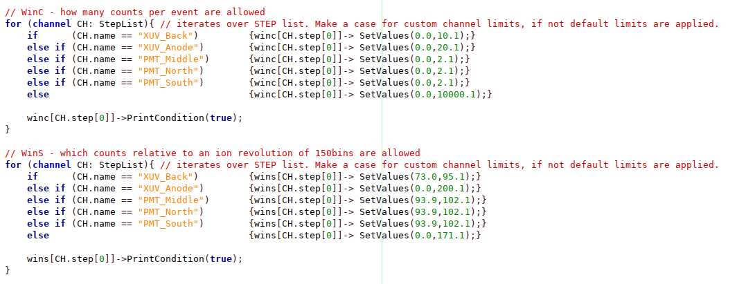
The WinC conditions are applied to all histograms under the folder "Analysis/Histograms/0_Raw/Scaler"
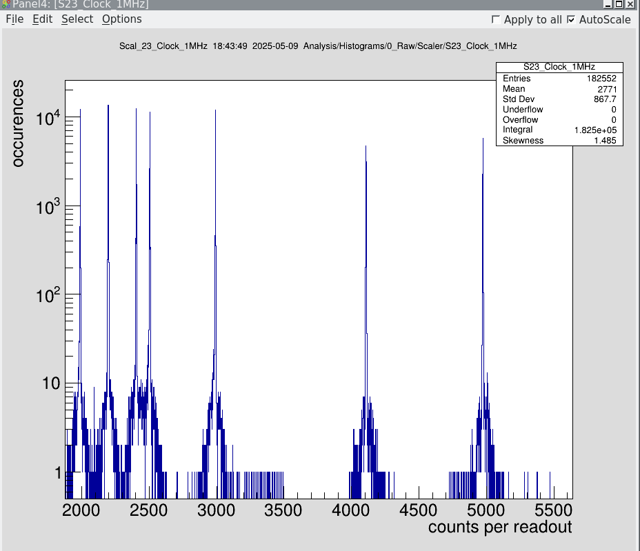
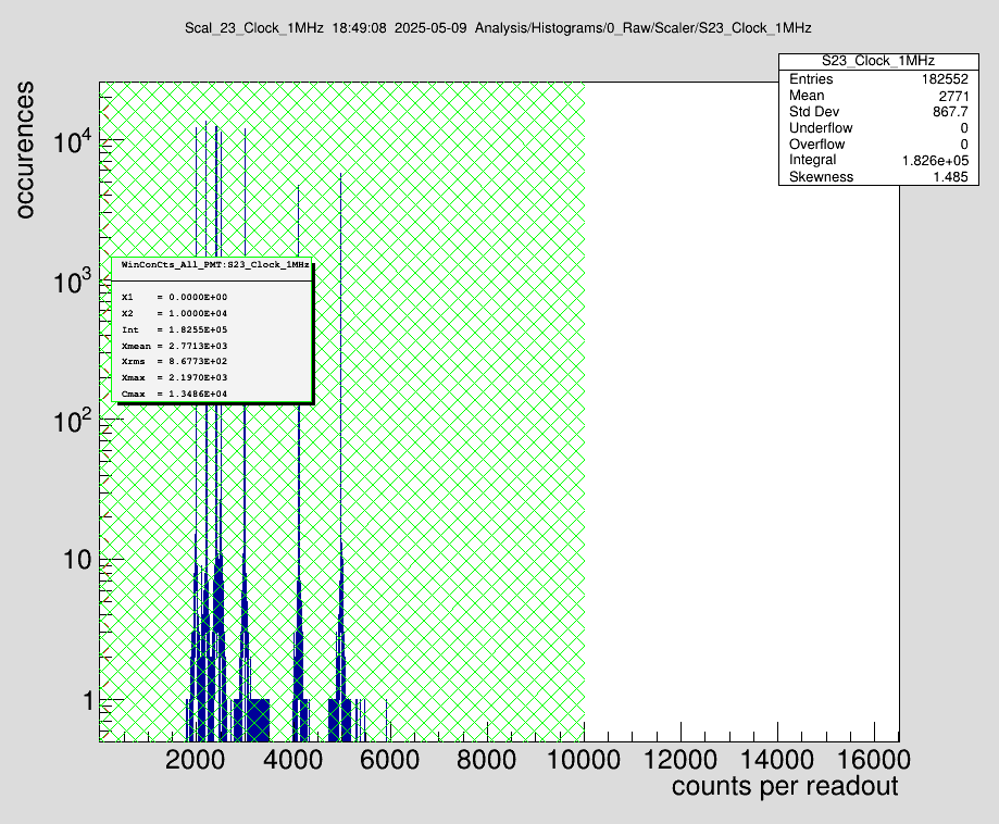
Important note: Particularly dangerous is the "WinC" condition (Attachment 2), which tests whether an unexpected (high) number of hits was recorded in a single event. An exemplary raw spectrum of the 1MHz reference is shown in Attachment 3. In Attachment 4 the same spectrum is overlayed with two WinC conditions (red and green). While the red condition would reject every hit for further analysis, the green window would allow every recorded hit to be processed in further analysis steps.
The WinS conditions are applied to all histograms under the folder "Analysis/Histograms/3_TDC/Bins/accumulated". They define the phase interval relative to the bunching HF, within which hits are processed in the histograms under "Analysis/Histograms/4_LaserSteps"
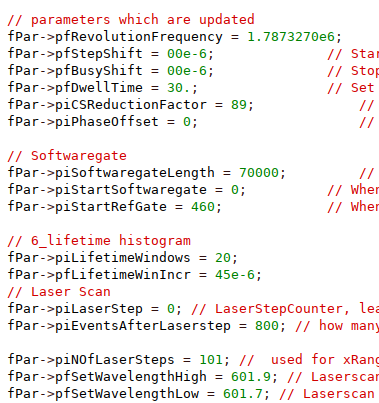
In the SetParameters.C file the most important settings are:
|
pfRevolutionFrequency | Must coincide with the revolution frequency (Not the bunching frequency!) | |
piCSReductionFactor | Setting of the rate divider, which is applied before feeding into the VUPROM as stop trigger of the TDC channels | |
pfDwellTime | Number of laser shots accumulated within one laser step | |
piSoftwaregateLength | Defines how many common stops are used to fill "Analysis/Histograms/4_LaserSteps/signal" | |
piNOfLaserSteps | Must coincide with the number of laser steps in Medusa
|
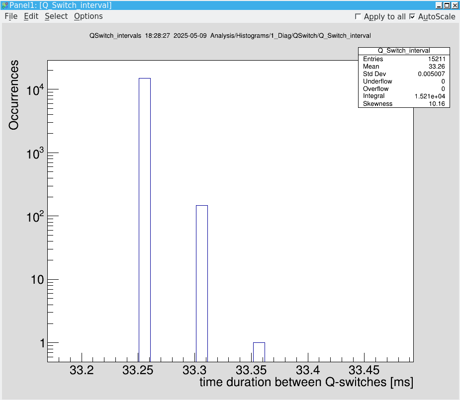
The parameter pfRevolutionFrequency and piCSReductionFactor define the display behavior of the time-resolved spectra. If you expect to observe bunches, check them. Another indicator for an erroneous selection is that the interval of the Q-Switch (laser shot) deviates from 1/30Hz = 33ms. The corresponding histogram can be found at "Analysis/Histograms/1_Diag/QSwitch/Q_Switch_interval" |
| Attachment 1: QSwitchDiagnose.png
|
|
| Attachment 2: SetConditions.png
|
|
| Attachment 3: MHzScaler.png
|
|
| Attachment 4: MHZWinC.png
|
|
| Attachment 5: SetParameters.png
|
|