| ID |
Date |
Author |
Category |
Subject |
|
1
|
Fri Apr 25 15:45:39 2025 |
Jan Glorius | DAQ | DR DAQ - MBS & Go4 |
The DR DAQ is located in AP Messhuette, here is the basic info.
MBS
node: x86l-151 (NUC)
user: litv-exp
screen session: DRdaq
MBS location: /esr/usr/litv-exp/MVLC/2025_DR_ESR (use symbolic link: /esr/usr/litv-exp/currentDAQ)
enter DAQ session with: /esr/usr/litv-exp/MVLC/2025_DR_ESR/daq.sh or ./daq.sh in the dir
kill and restart DAQ with: /esr/usr/litv-exp/MVLC/2025_DR_ESR/daqstart.sh or ./daqstart.sh in the dir
Recorded data:
WR timestamp
8 trigger types available
32 scaler channels available
Go4
PC: x86l-202 (but any with go4-login should work)
user: litv-exp (or any other)
MBS location: /esr/usr/litv-exp/go4/2025_ESR_DR_v0
path on lxg-machines: /lynx/Lynx/esr/usr/litv-exp/go4/2025_ESR_DR_v0
VNC server on x86l-202 can be used for Go4 or mvme if needed. Simply use the tigervnc icon "VNC x86l-202" on lxg-desktops of litv-exp.
RFIO & ESR-NAS
The data is stored via an rfio server (atprfio.gsi.de) on the ESR-NAS. The local folder on the NAS is /mnt/raw.data/2025_DRALS_Brandau/
The entire /mn/raw_data folder can be mounted to /esr/usr/litv-exp/exp_mnt/data.ESR on any x86l-XXX machine by using the alias "mountESR" or "sshfs -o directport=7777 atprfio.gsi.de:/mnt/raw.data /esr/usr/litv-exp/exp_mnt/data.ESR". |
|
Draft
|
Wed Apr 30 19:59:18 2025 |
Carsten | DAQ | DR_DAQ |
      	enum{TRIG_INJECTION=1,
	    TRIG_NEWRAMP=2,
	    TRIG_NEWVOLTAGE=3,
	    TRIG_VOLTAGE_SUB1=4,
	    TRIG_VOLTAGE_SUB2=5,
	    TRIG_VOLTAGE_SUB3=6,
	    TRIG_VOLTAGE_SUB4=7,
//	    TRIG_VOLTAGE_SUB5=8,
//	    TRIG_VOLTAGE_SUB6=9,
//	    TRIG_VOLTAGE_SUB7=10,
	    TRIG_ENDOFRAMP=8, //presently 20 Hz MVLC
	};

        double  f_ParticleDetSA_sc; // 1: Particle Counter SA -*
        double  f_ParticleDetNA_sc; // 2: Particle Counter NA -*
		double  f_ParticleDetNI_sc; // 3: Particle Counter NI -*
		double  f_Injection_sc; // 4: Injection in Scaler -*
		double  f_NewRamp_sc; // 5: New Ramp in Sc -*
		double  f_NewStep_sc; // 6: New Step in Sc -*
		double  f_ICur_sc; // 7: Ion Current in Sc -*
		double  f_tm_sc; // 8: 1MHz  -*
		double  f_dummy09_sc; // 9:
		double  f_HVDivider_sc; // 10: HV drifttubes, measured with divider -*
		double  f_dummy11_sc; // 11:
		double  f_ECurrent_sc; // 12: Electron Current Cooler -*
		double  f_CoolHV_sc;// 13: Voltage of Electron Cooler -*
		double  f_dummy14_sc; // 14:
		double  f_dummy15_sc; // 15:
		double  f_tm100Hz_sc;// 16: 100 Hz from MVLC IO
        double  f_dummy17_sc; // 17:
        double  f_dummy18_sc; // 18:
        double  f_dummy19_sc; // 26:
        double  f_dummy20_sc; // 27:
        double  f_dummy21_sc; // 28:
        double  f_dummy22_sc; // 29:
        double  f_dummy23_sc; // 30:
        double  f_dummy24_sc; // 31:
        double  f_sub1_sc; // 25: Subtrigger 1 sc
        double  f_sub2_sc; // 26: Subtrigger 2 sc
        double  f_sub3_sc; // 27: Subtrigger 3 sc
        double  f_sub4_sc; // 28: Subtrigger 4 sc
        double  f_sub5_sc; // 29: Subtrigger 5 sc
        double  f_sub6_sc; // 30: Subtrigger 6 sc
        double  f_sub7_sc; // 31: Subtrigger 7 sc
double f_dummy32_sc; // 32: |
|
3
|
Mon May 5 11:29:28 2025 |
Rodolfo, Simon, Nils, Volker | Detectors | PMTs |
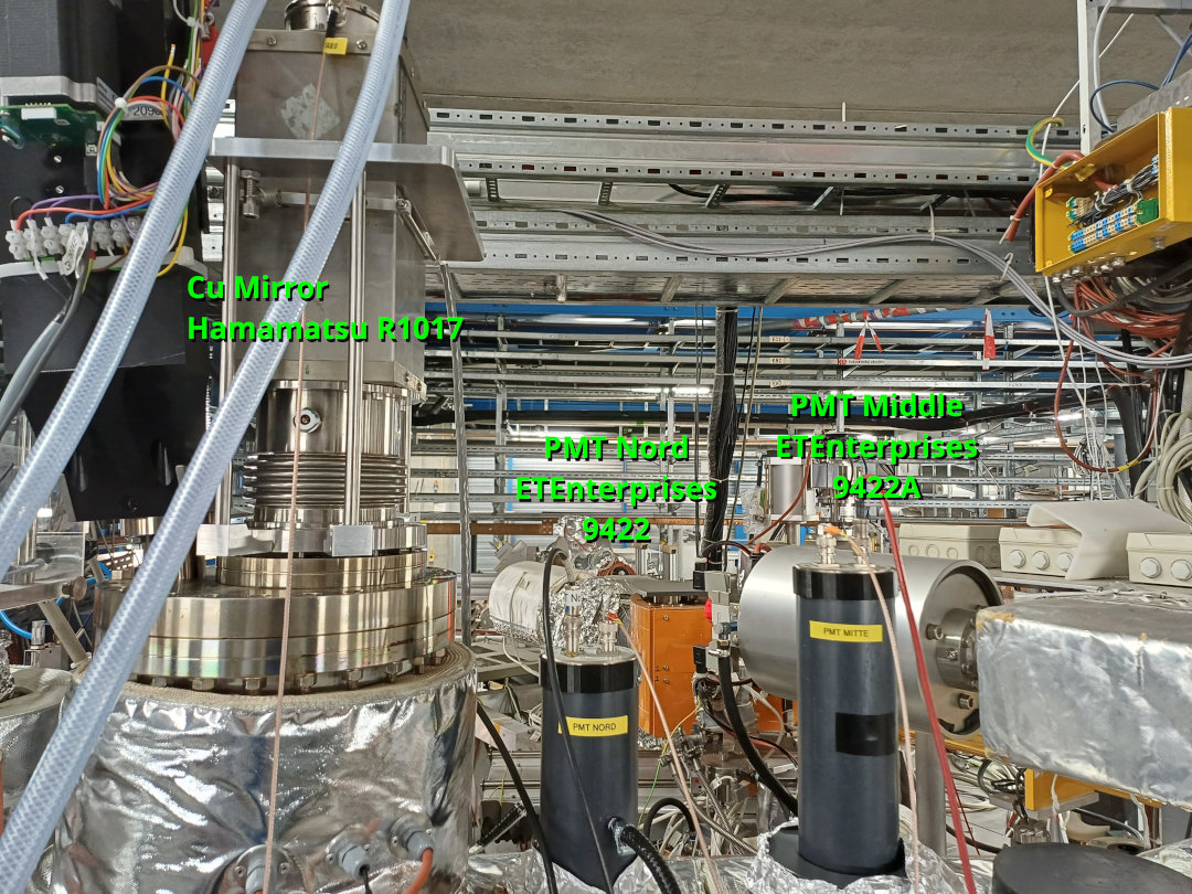
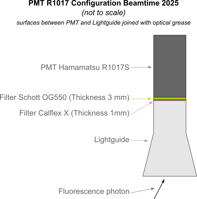
These are the PMTs installed at the optical detection region:
|
Label | Hersteller | Model | S.N. | Sensitivity | Operation voltage
| |
Cu-Mirror | Hamamatsu | R1017 (sel) | NA2313 | Infrared | -1300 V
| |
PMT Nord | ET Enterprises | 9422 | 1042 | UV | -1500 V
| |
PMT Middle | ET Enterprises | 9422A | 1001 | UV | -1700 V
|
|
| Attachment 1: SolarBlind_ET_9422_SN1042.pdf
|
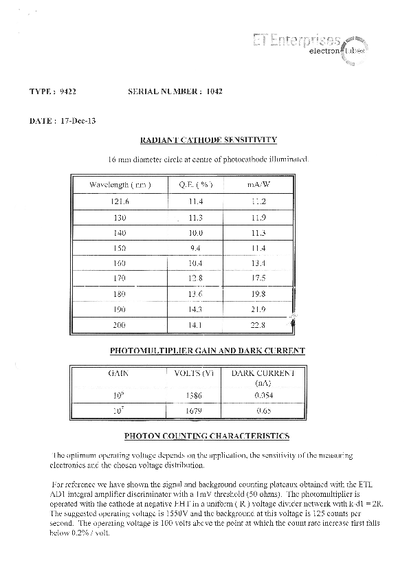
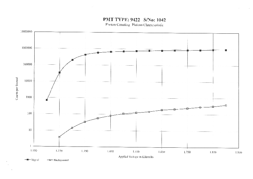
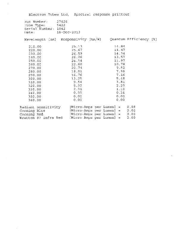
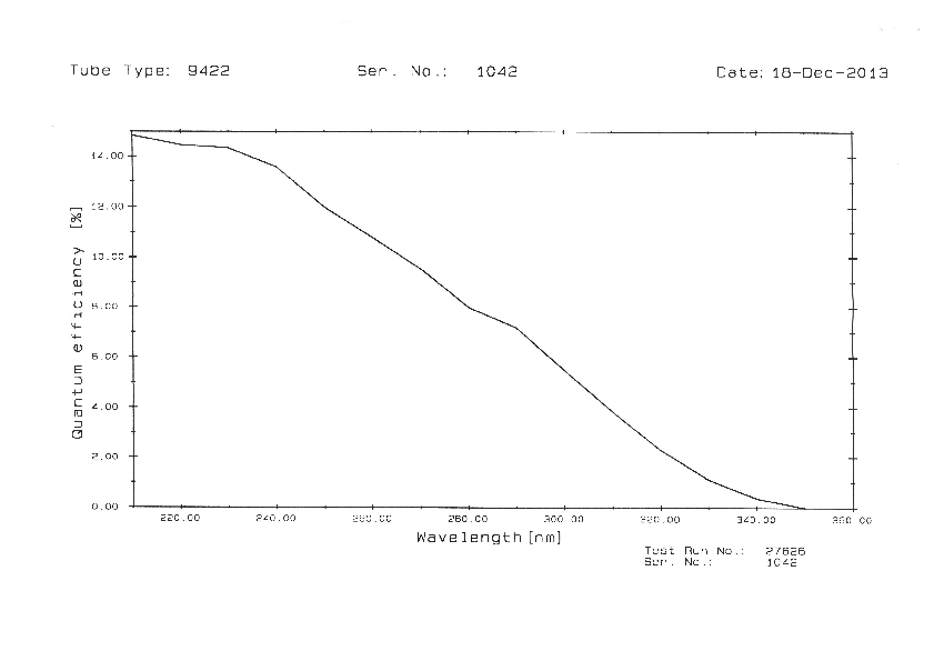
|
| Attachment 2: ThornEmi_PMT9422A_SN1001_(1987).pdf
|
-0.png)
-1.png)
-2.png)
|
| Attachment 3: PMT_Arrangement_Libelle2025.jpg
|
|
| Attachment 4: PMT_R1017_Configuration_Beamtime2025.png
|
|
|
4
|
Mon May 5 16:26:07 2025 |
Carsten | DAQ | DR Computer Names and IPs |
Computers used for control of HV amplifiers and DR microcontrollers are
- main control (big Philips monitor): sadpc058.gsi.de - 140.181.98.68
- NUC in ESR (DAC and HV divider ADC) : sadpc.gsi.de - 140.181.80.66
- Digilent scope in ESR (requires Digilent software installed, no user required): atpdev015.gsi.de - 140.181.82.76
- Seuencer NUC in Messhuette : NN - 140.181.92.75
only user on these machines: dr_esr (ask for PW)
DR go4 /mbs is controlled on lxg3113 under user litv-exp
(Details in post 1), more details concerning directory of Go4 etc.yet to come. |
|
5
|
Mon May 5 21:13:29 2025 |
Rodolfo | Laser | Collimation of laser beam |
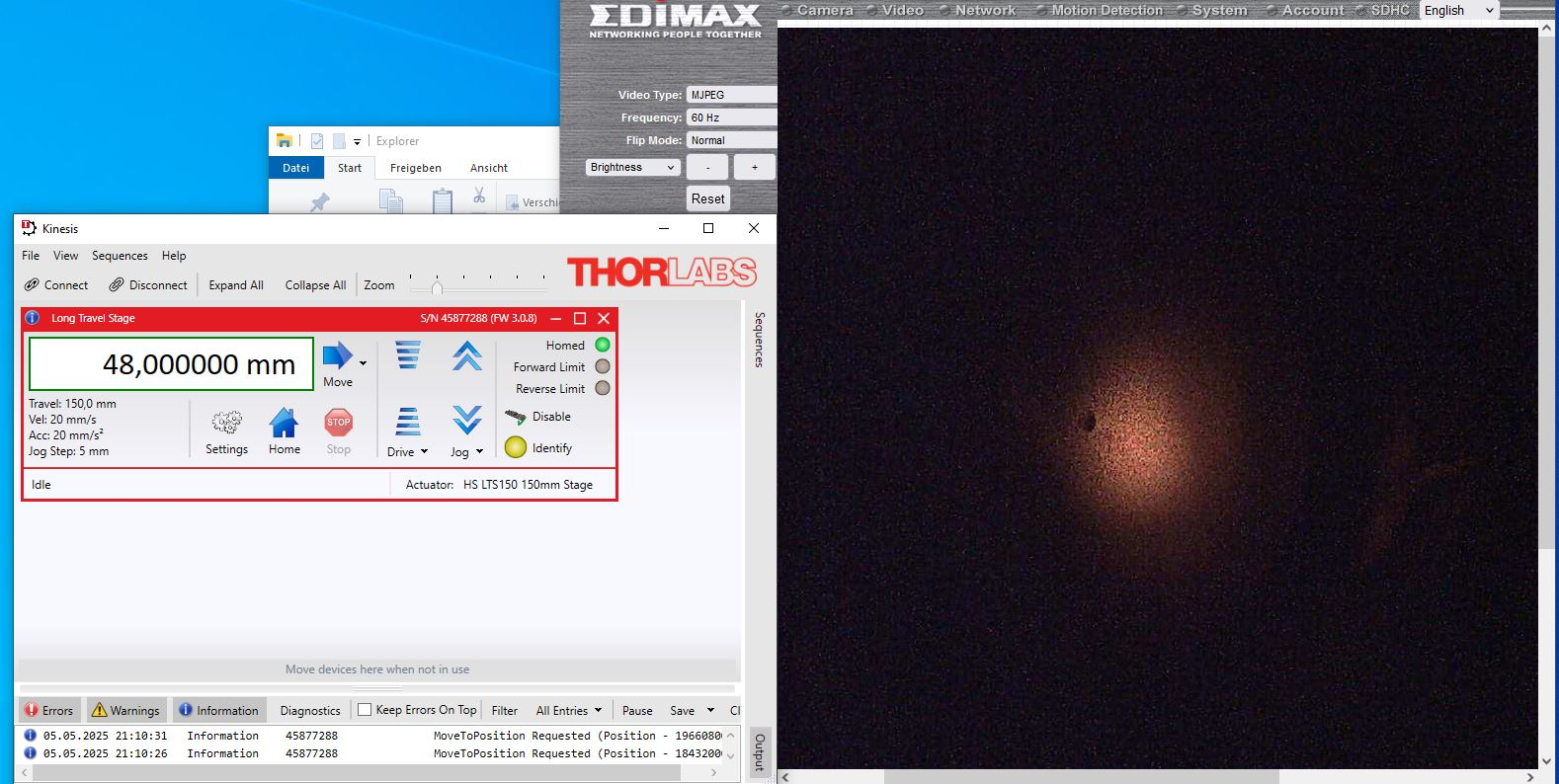
Here some parameters for the collimation of the laser beam
Periscope:
- Planconcav -500 mm
- Planconvex +1000 mm
Distance between both lenses: 504 mm.
Long Travel Stage @ 48,0 mm
The screnshot shows the laser spot at the screen "SO-Arc". |
| Attachment 1: Cobra593nm_Laserbeam_Collimation_2025-05-05.JPG
|
|
|
6
|
Tue May 6 15:35:12 2025 |
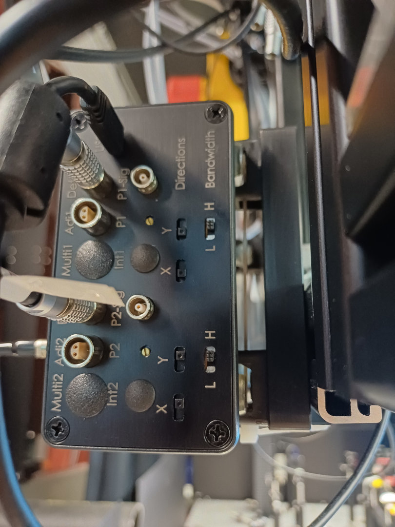
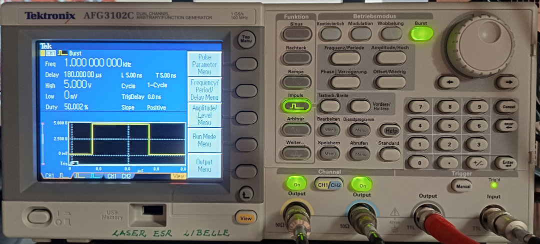
Rodolfo, Konstantin | Laser | MRC Settings |
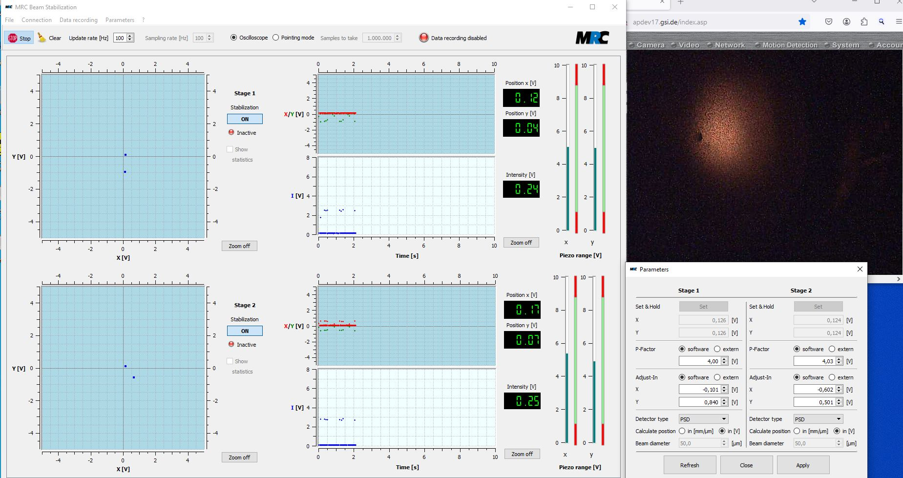
Following settings (P-Factor, Directions and Bandwidth) are used for the laser beam stabilization. Full energy (ca. 150 mJ @ 593 nm).
The triggers for the MRC are generated by AFG3102C. The settings (the same for both CH1 and CH2) are saved under "Abrufen / Setup2" |
| Attachment 1: MRC_Settings_Cobra593_VolleLeistung_2025-05-06.JPG
|
|
| Attachment 2: MRC_Controller_Settings_2025-05-06.jpg
|
|
| Attachment 3: AFG3202C_Settings.jpg
|
|
|
7
|
Wed May 7 14:02:58 2025 |
Konstantin | DAQ | DAQ Folder |
The folder of the data acquisition are:
Go4 (atplaser@lxg1297): ~/go4/drals
MBS (atplaser@r4l-41): ~/mbsrun/G038/DRALS |
|
8
|
Wed May 7 17:29:19 2025 |
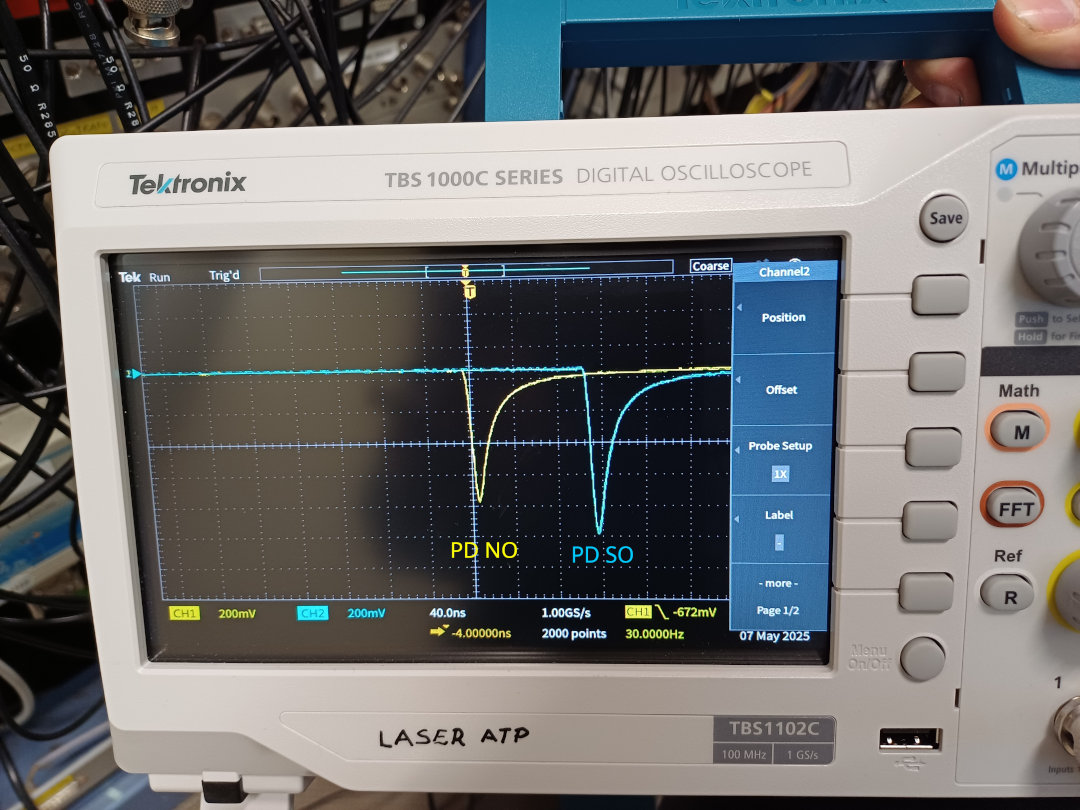
Rodolfo, Simon | DAQ | Fast Photodiodes |
Signal for the fast photodiodes. The laser beam
- enters at the Nord-Ost (NO) Arc and
- leaves at the Süd-Ost (SO) Arc.
The photodiodes themself are located inside the laser towers. |
| Attachment 1: FastPD-Signals_Messhütte_2025-05-07.jpg
|
|
|
9
|
Wed May 7 20:31:52 2025 |
Carsten | DAQ | DRALS cabling (DR part) |
Green Corner, patch panel to ESR
All signals from/ to ESR TTL 5V.
Signals are GND decoupled with grey boxes! Don't use the signals directly.
[1] New Ramp (NR) / Meas Gate
[2] New Step (NS)
[3] End of Ramp (ER) / COOL
[4] to ESR: Start Measure Trigger
[5] to ESR: Laser Trigger (~ 30 Hz)
[6] MEAS0
[7] MEAS1
[8] VFC
Patch Panel "Green Corner" (DR) <-> "Blue Corner" (Laser)
Signals are neg NIM unless otherwise indicated
(i.e. the two signals from/to the DR Trigger side need to be TTL)
[11] to DR side: Laser Trigger (TTL) => to do => done
[12] from DR side Injection; signal comes from DR DAQ!!! => to do
[13] Meas Gate
[14] VFC
[15] to DR side: Part Det South (Cooler) => to do
[16] to DR side: Part Det North (Gas jet) => to do
[25] COOL
[26] MEAS0
[27] MEAS1
[28] New Step (NS)
[29] SubTrig 1
[30] SubTrig 2
[31] SubTrig 3
[32] SubTrig 4
NACOM 1 => Signals ar ORed as Master Readout Trigger and Counted in DRALS Scaler 9 to 16
[1] COOL => SC Ch9
[2] MEAS0 => SC Ch10
[3] MEAS1
[4] New Step (NS)
[5] SubTrig 1
[6] SubTrig 2
[7] SubTrig 3
[8] SubTrig 4 =Sc Ch16
The Measgate Signal (logic high when in measurement window) is ANDed with 100 kHz clock. The strobed signal is put in DRALS DAQ ( to do). |
|
10
|
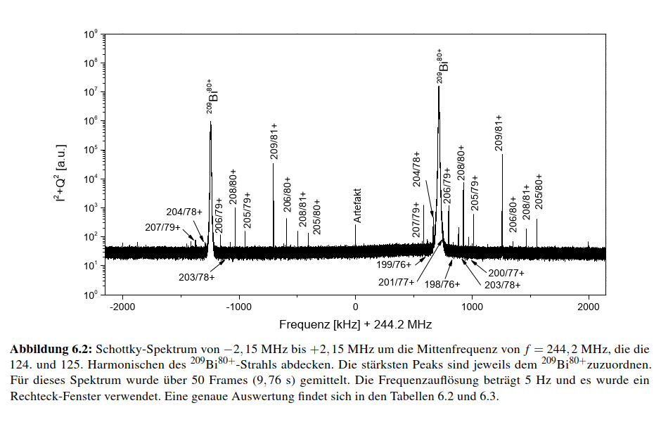
Thu May 8 10:11:37 2025 |
Carsten | General | Schottky spectrum ( 2 Harmonics) from the earlier 209Bi80+ Libelle run (thesis C. Trageser) |
|
| Attachment 1: Schottky_Libelle_on_209Bi80.png
|
|
|
11
|
Thu May 8 10:21:10 2025 |
Carsten | | Link to thesis of C. Trageser NTCAP/ Automated Schottky analysis of cooler voltage and space charge) |
The thesis of Christian might be helpful w.r.t. to energy calibration as it shows how to link Schottky frequency to ion energy (might be required since in DRALS the exact ion energy will be difficult to derive from voltage measurements only).
Cf., chapter 6 (thesis is in German)
Link: Thesis C. Trageser |
|
12
|
Thu May 8 13:33:13 2025 |
Rodolfo, Simon | Laser | Camera @ South-West Screen |
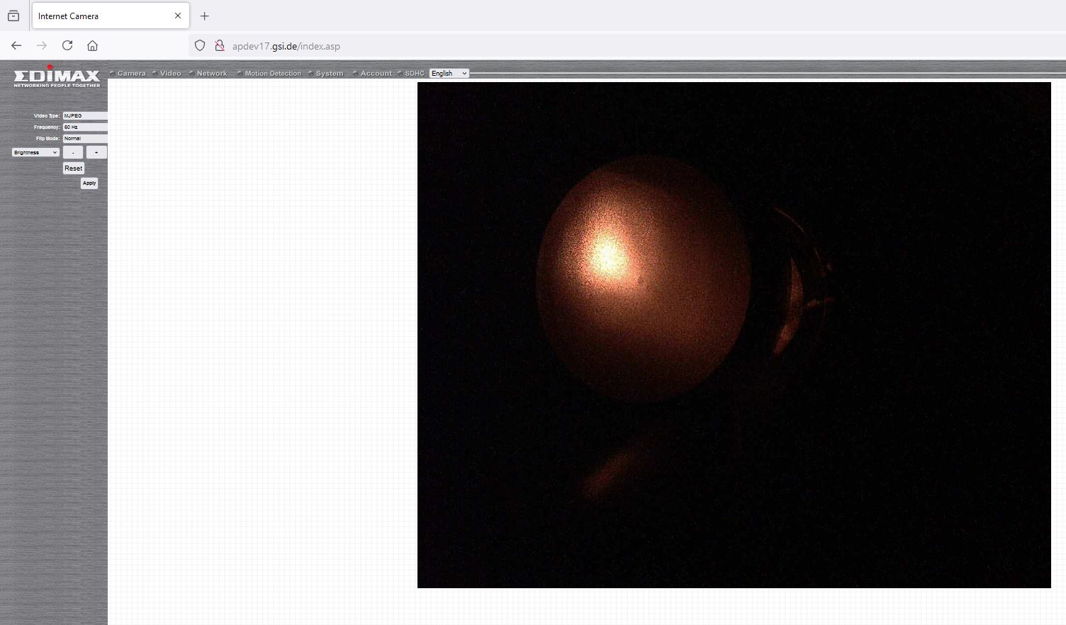
Network camera to monitor the position of the laser beam after the electron cooler.
apdev017.gsi.de
user: admin
password: 1234 |
| Attachment 1: Laserbeam@SW-Screen_2025-05-08.JPG
|
|
|
13
|
Thu May 8 17:23:51 2025 |
Shahab | General | Schottky TV |
setup Schottky TV:

connect to atppc030 using:

xfreerdp /u:atplaser /v:atppc030.gsi.de /w:1920 /h:1060

PW: given at label@LXG1297

this can be done also from the TCL computers

inside you open OBS Studio

then choose Video-Capture Device and both USB3 devices. |
|
14
|
Thu May 8 19:35:18 2025 |
Simon | | PMT count rates |
I tested the PMTs and tried to reduce the background signal as far as possible.
|
PMT | voltage (V) | count rate (Hz)
| |
Mid | 1700 | 1200
| |
North | 1500 | 900
| |
Cu | 1300 | 1400
|
PMT Mid count rate strongly fluctuates.
Turning the light on in the ESR has no influence on Mid and North but increases the rate for Cu by 200Hz. |
|
15
|
Thu May 8 22:50:37 2025 |
Carsten | DAQ | Preliminary Timing Settings |
Tentatively:
DAC:
Meas Gate: 8000 ms (8000000 us)
Cool Time: 16800 us
Meas0,1: 16800 us
Ramp Time: 3000 us
SubTrigger (us):
1: 5500
2: 2000
3: 2200
4: 2400
5: 200 (not wired)
6: 200 (not wired)
7: 200 (not wired)
These values together with 30 Hz produce nice Timer spectrum with separated peaks. |
|
16
|
Thu May 8 23:36:19 2025 |
Konstantin | DAQ | Fileserver |
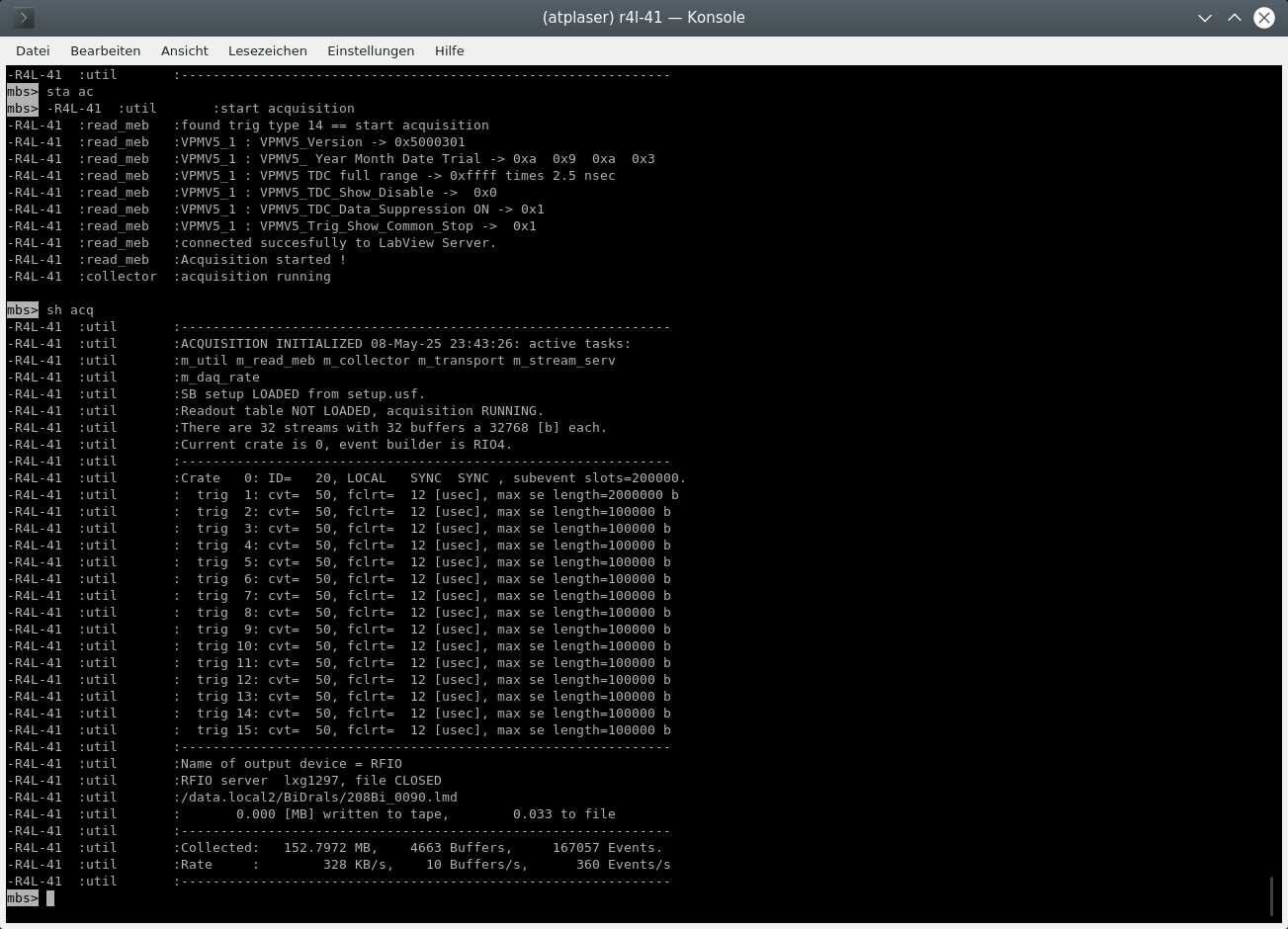
To save files, the rfio-server must be started on lxg1297 in the folder /data.local2/BiDrals/. The file structure is
/data.local2/BiDrals/208Bi_XXX.lmd
where XXX is the current file number. To connect the mbs client to the file server, run the command
@connectdisk
on mbs. A file is opened and closed by running commands
@openfile
@closefile
respectively. To test whether a file is opened run
show acquisition
In the last rows of the output you will find the connection details and the status of the output file (see attachement). The attached screenshot displays that the RFIO server is connected and the file /data.local2/BiDrals/208Bi_090.lmd has been closed. |
| Attachment 1: MBS_SshowAcq.png
|
|
|
17
|
Fri May 9 00:56:07 2025 |
Konstantin | DAQ | First Files |
| Files 91 + 92 were recorded with the Trigger logic as explained in ID 15. The laser was scanned from 593 to 592 in 101 steps. 100 laser steps were accumulated at each step. Bunching HF was synthesized by an AFG with a frequency of 1.787327MHZ and divided by 89 |
|
18
|
Fri May 9 14:21:18 2025 |
Rodolfo | Accelerator | T-Scrapers |
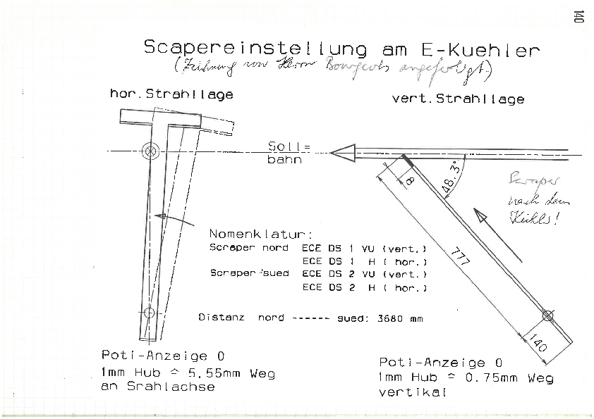
Information about the T-Scrapers at the ESR Electron Cooler. The width of the scraper is approx. 9 mm.
There was some issue about the Scraper GECEDS2VU. Herr Boywitt solved this issue and shortly communicated the procedure about how to move it.
Nils and me talked today with Sergey. He mentioned to go to position "-5 mm". Herr Boywitt wrote "-50", see below.
Mail vom 10.04.2025 um 13:26 Uhr.
Hallo alle,
wir haben den ESR Scraper instand gesetzt.
Am mittenkontakt hatte sich eine Verbindung gelöst, weiterhin haben wir den Mittenkontaktschalter neu justiert.
Der Antrieb sollte , um den Mittenkontaktschalter auszulösen, von der Endlage außen auf die Position -50 gefahren werden.
Viele Grüße
Robert |
| Attachment 1: Scrapereinstellung_am_ESR.pdf
|
|
|
19
|
Fri May 9 17:47:07 2025 |
Konstantin | DAQ | HV Divider |
| The HV voltage applied at the high-voltage platform of the electron cooler can be observed at HV-divider. |
|
20
|
Fri May 9 18:34:08 2025 |
Konstantin | DAQ | Important diagnoses of analysis parameters |
The filling of some histograms in the go4 analysis framework is controlled by the SetParameters.C and SetConditions.C files.
The WinC conditions are applied to all histograms under the folder "Analysis/Histograms/0_Raw/Scaler"
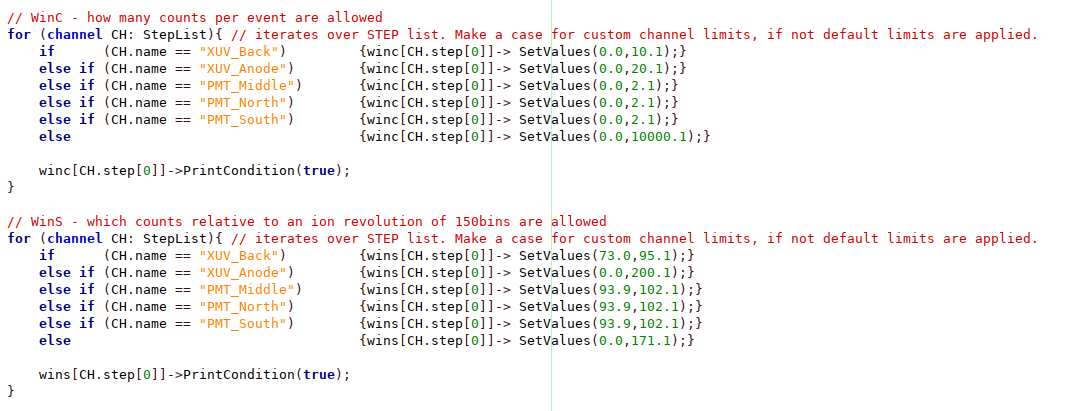
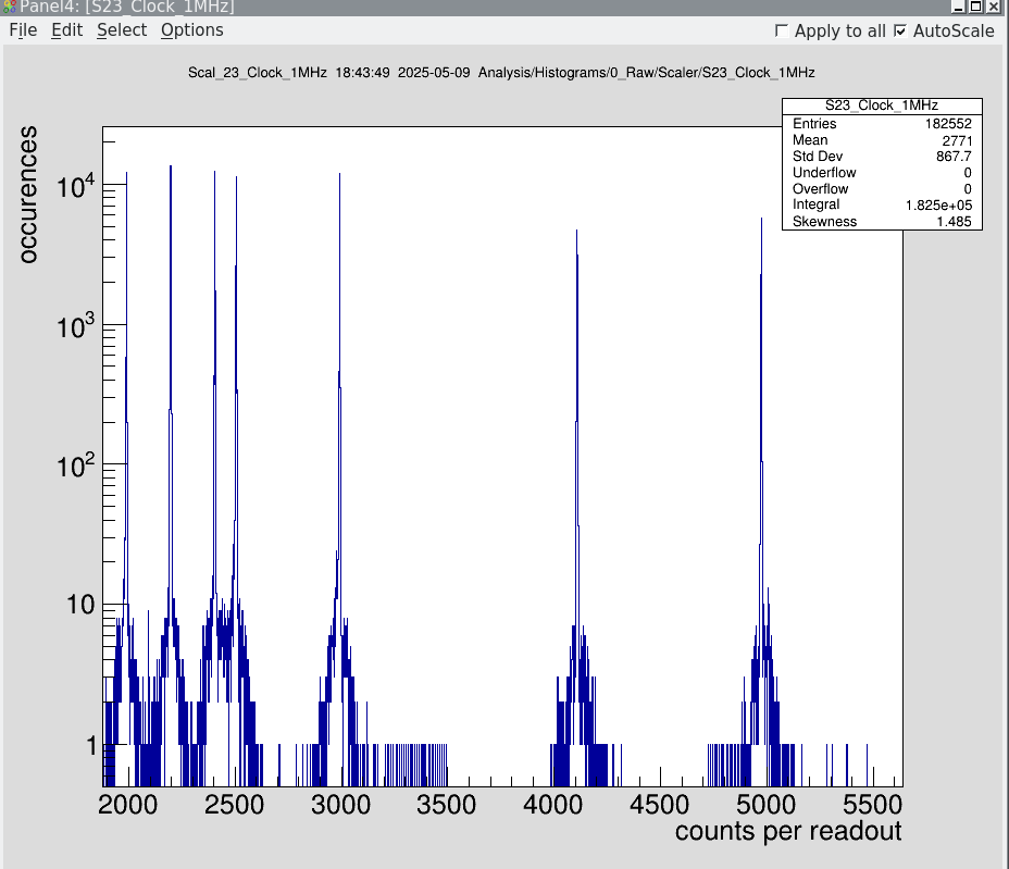
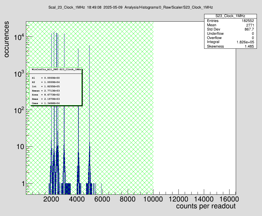
Important note: Particularly dangerous is the "WinC" condition (Attachment 2), which tests whether an unexpected (high) number of hits was recorded in a single event. An exemplary raw spectrum of the 1MHz reference is shown in Attachment 3. In Attachment 4 the same spectrum is overlayed with two WinC conditions (red and green). While the red condition would reject every hit for further analysis, the green window would allow every recorded hit to be processed in further analysis steps.
The WinS conditions are applied to all histograms under the folder "Analysis/Histograms/3_TDC/Bins/accumulated". They define the phase interval relative to the bunching HF, within which hits are processed in the histograms under "Analysis/Histograms/4_LaserSteps"
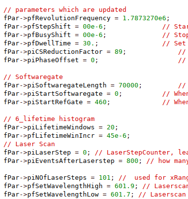
In the SetParameters.C file the most important settings are:
|
pfRevolutionFrequency | Must coincide with the revolution frequency (Not the bunching frequency!) | |
piCSReductionFactor | Setting of the rate divider, which is applied before feeding into the VUPROM as stop trigger of the TDC channels | |
pfDwellTime | Number of laser shots accumulated within one laser step | |
piSoftwaregateLength | Defines how many common stops are used to fill "Analysis/Histograms/4_LaserSteps/signal" | |
piNOfLaserSteps | Must coincide with the number of laser steps in Medusa
|
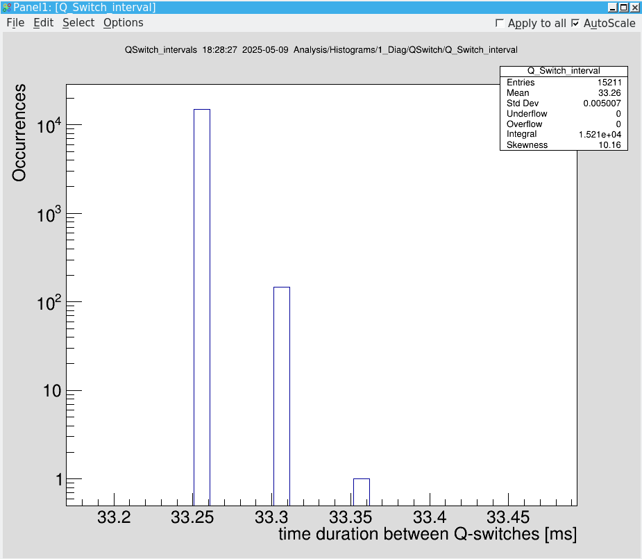
The parameter pfRevolutionFrequency and piCSReductionFactor define the display behavior of the time-resolved spectra. If you expect to observe bunches, check them. Another indicator for an erroneous selection is that the interval of the Q-Switch (laser shot) deviates from 1/30Hz = 33ms. The corresponding histogram can be found at "Analysis/Histograms/1_Diag/QSwitch/Q_Switch_interval" |
| Attachment 1: QSwitchDiagnose.png
|
|
| Attachment 2: SetConditions.png
|
|
| Attachment 3: MHzScaler.png
|
|
| Attachment 4: MHZWinC.png
|
|
| Attachment 5: SetParameters.png
|
|
|
21
|
Sat May 10 00:52:21 2025 |
Finn, Simon, Konstantin, Rodolfo | DAQ | Bunching - ammendment late shift |
Some 209Bi80+ beam was provided for tests measurement over the weekend. Currently the beam is bunched at the second harmonic, corresponding to a bunching frequency of 3.87421MHz and a revolution frequency of 1.937105MHz. The setting of the rate dividers were 2 and 99. Two is important since we are working with the second harmonic, and 99 provides approximately 20kHz, which is expected by the DAQ. The measurement of the frequency was performed in the Manipulation subchain SC8.
Rodolfo. In SetParameters.C was written another value (namely: 1.9370959 MHz). I changed this value to 1.937105 MHz. |
|
22
|
Sat May 10 03:32:18 2025 |
Finn, Simon | General | Beam not bunched (?) |
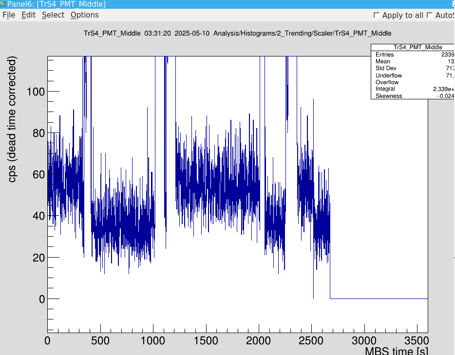
We think the beam in the ESR is not bunched. There is a clear difference in PMT signal if ions are in the ESR compared to no ions (see screenshot of scaler PMT mid, high level with ions, low level without) but we see no structure of an ion bunch (see screenshot of accumulated bins).
We also increased the accumulation to 10 injections, still no bunch visible.
We double checked the frequency value of the HF cavity mentioned in the last ELOG entrance. |
| Attachment 1: Bildschirmfoto_2025-05-10_03-31-28.png
|
|
| Attachment 2: Bildschirmfoto_2025-05-10_03-31-28.png
|

|
|
23
|
Sat May 10 03:46:57 2025 |
Finn, Simon | Detectors | PMT north |
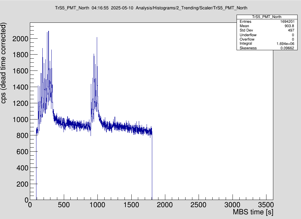
In contrast to PMT Mid, the difference between ions and no ions in the ESR (see screenshot scaler) is not visible. Signal gets higher with injection and shows some kind of exponential decay afterwards.
Beam was dumped at 500 and 1200s. Even after the dump, the signal steadily drops.
We tried to adjust the threshold such that a difference between ions in the ring and not becomes visible, but even with a minimal threshold no effect was visible. |
| Attachment 1: Bildschirmfoto_2025-05-10_04-17-00.png
|
|
|
24
|
Sat May 10 03:54:46 2025 |
Finn, Simon, Carsten | General | Night shift sum up - ammendment day shift |
As the beam in the ESR is most probably not bunched, there was not much we could do. During the night shift we:
- adjusted the threshold of the PMTs mid and north with beam in the ring
- found that the delay generator for PMT mid is broken, so the timing is off and needs to be remeasured
- tried to see the beam with PMT north, but with no success. Maybe with bunched beam this will be possible.

We turned off the PMTs, stopped mbs and the ESR pattern, notified HKR and left at 5am.


===> 10.05.12:30 (Carsten)
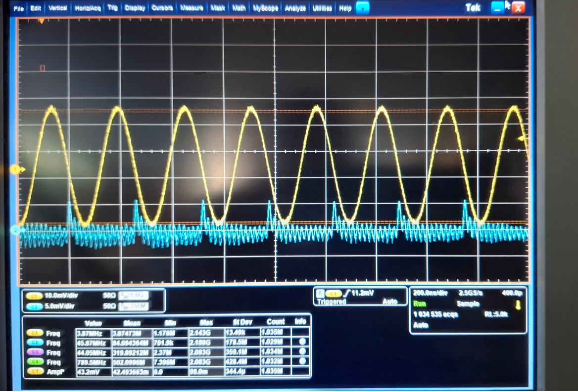
I checked the bunching in the HKR - the beam is bunche - see attached Foto from scope in HKR.
The blue line shows (the "zig-zag") that the ion beam is very well bunched, and that bunching frequency and cooling energy are "well matched". |
| Attachment 1: Bunching_Screenshot_2025-05-10_125634.png
|
|
|
25
|
Sat May 10 12:58:54 2025 |
Carsten | Detectors | Scrapers do not work reliably / Scraper positions for further tests |
I tried scraping with pressurized-air devices in order to verify the beam poistion. All 4 devices that we use do not work reliable (at least when driven "manually" via Device Control).
1) Sometimes they do not reach the set position
2) Sometimes they overshoot the set position but "oscillate" back to finally reach the set value. EVEN with small step like 5mm the drive moves then 15m in and 10 mm back (or even further?)
3) It seems (but difficult to verify to due 2) that position calibration is quite off.

In particular the latter behaviour makes it very difficult to locate the ion beam.  It seems to be possible to set up the particle detector for the primary beam but will make it very difficult if not impossible to set up 208Bi with the secondary beam.

The following value for "scraping" are thus to be taken with a grain of caution.
GE02DD2_G (Part Det behind cooler): beam is destroyd at -25 (at -30 ?)
GE02DS3HG (Scaper in south arc): beam is destrod at -4
GE01DD1AG (Capture North arc): beam is destroyed at about -30
GE01DD2IG (Ion North arc): even at "endlage innen" ion beam cannot be touched.

For further tests I try the following automated settings:

IN in in SC7, BP3
GE02DD2_G, GE02DS3HG, GE01DD1AG : -45
GE01DD2IG : 20

OUT in in SC10
GE02DD2_G, GE02DS3HG, GE01DD1AG : -120
GE01DD2IG : 120
(not fully out) |
|
27
|
Sat May 10 17:05:24 2025 |
Konstantin | Detectors | XUV detector and copper mirror control |
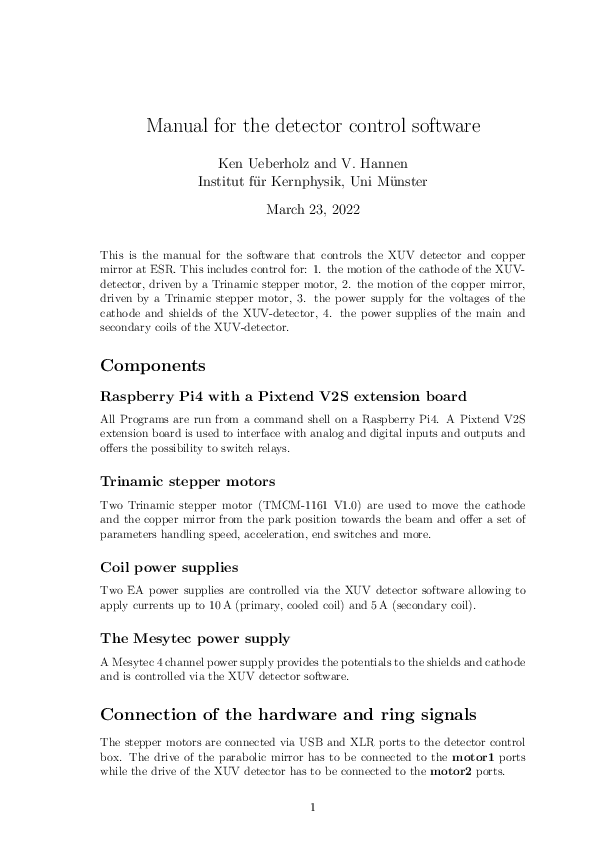
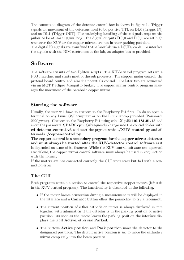
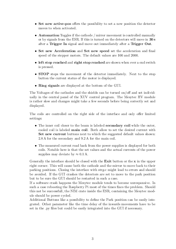
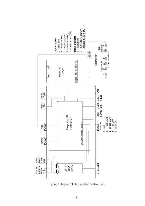
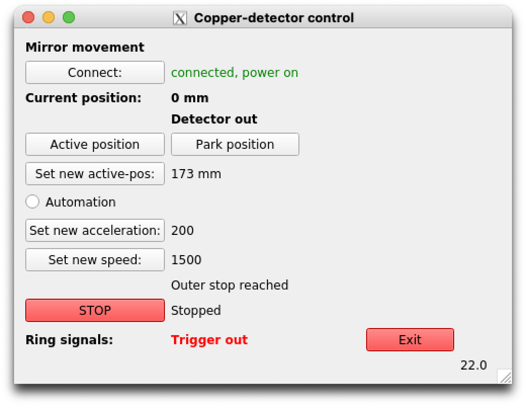
| I attach the manual of the XUV and copper mirror control software, which is hosted at the Raspberry Pi (140.181.91.15) below the optical detection region at ESR. The Motor position of the stepper motor is at 0mm, which corresponds to the outer park position. |
| Attachment 1: Manual.pdf
|
|
| Attachment 2: CopperMirrorControl.png
|
|
|
28
|
Sat May 10 17:47:50 2025 |
Carsten, Wilfried | Accelerator | Drifttube Cooling works |
The cooling ith a tentative DRALS pattern works well.
Cooling voltage in SC8 is now 905 V higher:
ESR manipulations -> Cooler maniuplations -> GECEBG1E is changed from +150V to +1055V. Please note the sign conventions. This means that the electrons are now 905V faster.
This is compensated by a DRALS pattern of -900 V (COOL) / 3300V (MEAS0/MEAS1). The -900V at the drifttubes decelerates the electrons.

The voltage is verified via the bunching pattern in the scope. The bunching signals look best in a flattop of about +1050V to 1060V. 1050V is the design value (1050V -900V = 150V). |
|
29
|
Sat May 10 20:14:47 2025 |
Rodolfo, Wilfried, Carsten | General | Lights in ESR |
The light (Beleuchtung) inside the Cave have been ON since probably yesterday evening (9. May) when Uli was inside the cave for fixing some issues.
We have now turned off the light.
Another possible reason for the non-observation of bunches might be that we probably have a large number of unbunched ions in the ring that are produced in the Be-target/stripper.
|
|
30
|
Sat May 10 20:53:17 2025 |
Rodolfo, Konstantin | Accelerator | Reading of E-Cooler Voltage |
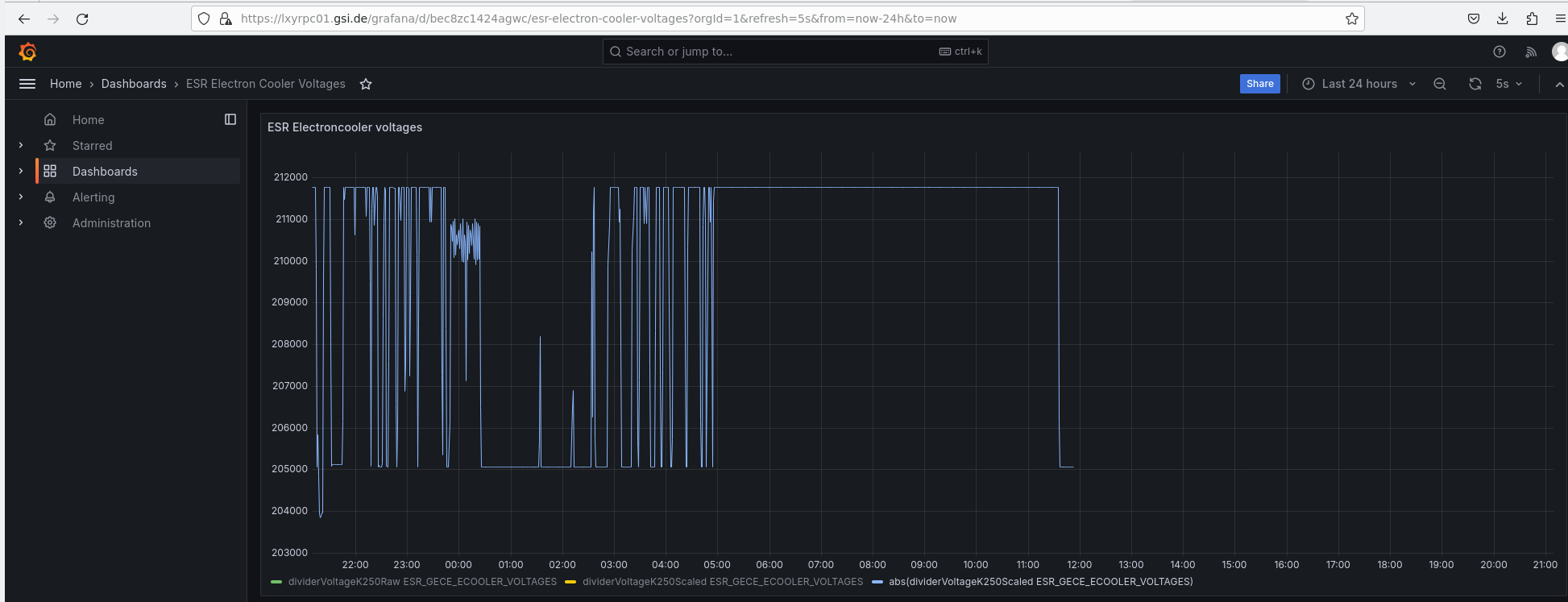
We do not have the reading of the electron cooler voltage. According to Grafana the reading of the voltage stopped at 11:53:00, when the voltage was 205070 V.
Konstantin tried to solve the issue remotely. He cannot access the Computer (a Raspi) remotely. Ping works, but it looks like SSH is not working. |
| Attachment 1: Grafana_ECoolerVoltage_Bildschirmfoto_2025-05-10_21-09-46.png
|
|
|
31
|
Sat May 10 22:47:29 2025 |
Konstantin | DAQ | HV Divider |
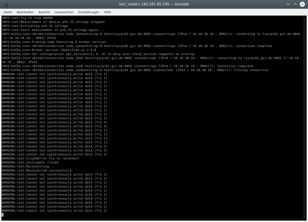
The readout of the hv dividers is running again. In order to restart the acquisition if it has crashed, connect to the raspberry pi and restart the analysis. Therefore, use the following procedure (Optional steps are indicated with (*)):
- ssh esr_cooler@140.181.95.195
- screen -r cooler_signals (Note: If this command ends with an error message, use "-R" instead of "-r". In this case the readout was not running and must be restarted (see below). Otherwise you should see something similar to the attachment. As long as warnings are printed everything works fine
 The program can be stopped by typing "stop" and pressing return.) The program can be stopped by typing "stop" and pressing return.)
- (*) cd Documents/electroncoolerelectricalsignals/
- (*) conda activate cooler_signals
- (*) python main.py -f <file name> -i <interval> (argument filename is the name of the log file and interval is the sending interval of the HV-divider)
|
| Attachment 1: HVReadout.png
|
|
|
32
|
Sat May 10 23:30:37 2025 |
Rodolfo | Accelerator | Ion Pumps at the target section |
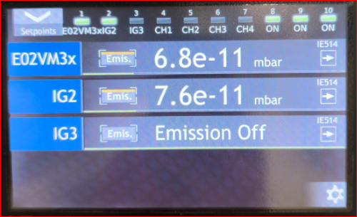
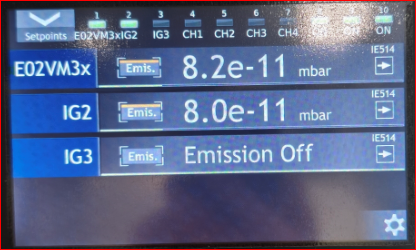
| The ion pumps (E02VP16i and E02VP17i) which nearby the optical detection region produce high count rate into the photomultipiers. Therefore they were turned off on May 5th by our colleague from UHV (Herr Mia). He checked the vacuum before (EIN) and after (AUS) turning off the pumps. |
| Attachment 1: Vakuum_IOP_EIN_2025-05-05.png
|
|
| Attachment 2: Vakuum_IOP_AUS_2025-05-05.png
|
|
|
33
|
Sun May 11 03:10:41 2025 |
Konstantin, Simon | Detectors | Bunched beam on PMT |
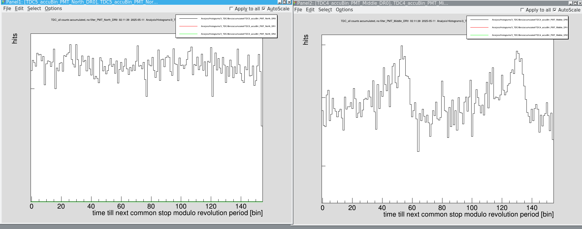
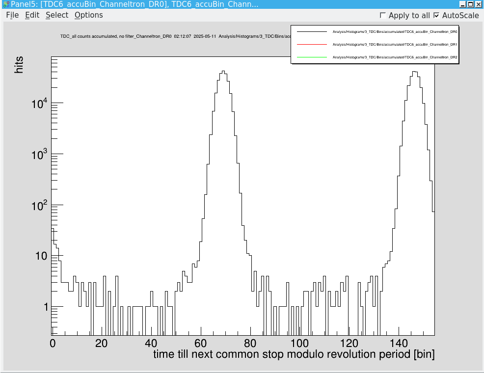
We checked again the time-resolved signal on the PMTs and after several minutes of accumulation we saw a the bunch shapes on PMT mid (att. 1 right) and also a tiny indication on PMT north (att. 1 left).
On the particle detector, the bunches are clearly visible (att. 2).
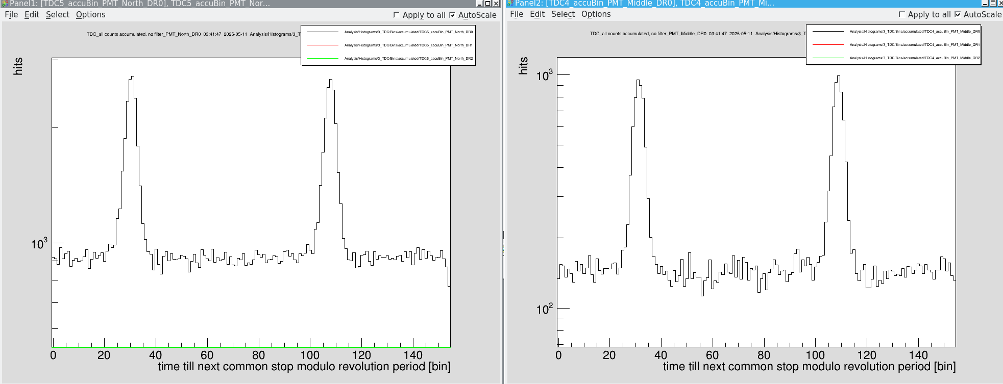
To improve the signal we turned on the nitrogen supply of the PMTs in order to reduce the photon absorption by air. This was indeed a game changer in order to identify bunches (att. 3) |
| Attachment 1: Bildschirmfoto_2025-05-11_02-11-44.png
|
|
| Attachment 2: Bildschirmfoto_2025-05-11_02-12-11.png
|
|
| Attachment 3: Bildschirmfoto_2025-05-11_03-41-52.png
|
|
|
34
|
Sun May 11 03:23:18 2025 |
Simon, Konstantin | Calibration | Delaytime measurement |
We performed another set of delay time measurements to substitude the broken channel of PMT middle. We did this in two step:
1.) Measurement of the total delay between the origin of a signal (AFG 10kHz, -50mV amplitude) and the detection directly before the DAQ after traveling through the long calibration cable (~50m) and the individual channel line. During this step we corrected the delay time if necessary by means of an OG 8000. This was only mandatory for PMT middle. We considered the traveling time of 46ns for all PMT detectors. We didn't measure the delay of PD North and Particle Detector south, since all other channels were fine and the delay after the OG 8000 were reasonable.
2.) Measurement of the delay within the OG 8000 octal gate generator.
|
| Total delay / ns | OG 8000 delay / ns | |
Photodiode North | - | 69.6 | |
Photodiode South | 1266.6 | 73.6 | |
PMT Middle | 1220.6 | 156.6 | |
PMT North | 1220.6 | 167.4 | |
PMT Copper | 1220.6 | 166.0 | |
Particle South | - | 337.6
|
|
|
35
|
Sun May 11 05:16:22 2025 |
Konstantin, Simon | Accelerator | Breeding of Lithium |
We measured the breeding efficiency of Li-like ions in the ESR and the rates are way below the expected 25%.
|
breeding time (min) | # after injection | # after breeding | efficiency
| |
1 | 1,48E+07 | 4E+05 | 0,0270
| |
2 | 1,33E+07 | 5E+05 | 0,0376
| |
3 | 1,37E+07 | 6E+05 | 0,0438
| |
4 | 1,38E+07 | 6E+05 | 0,0435
| |
6 | 1,40E+07 | 7E+05 | 0,0500
| |
8 | 1,46E+07 | 8E+05 | 0,0548
| |
10 | 2,31E+07 | 12E+05 | 0,0519
| |
15 | 1,44E+07 | 8E+05 | 0,0556
|
All measurements were taken with 1 single injection.
Edited by Carsten 2025-05-11:
A word of caution: Due an offset of the current transformer that changes easily with time I would question any reading below 1e6 ions. Even at 1e6 the error could vary from easily by 20 (?) percent.
Secnd comment: The efficiency cannot be deduced that way because before decelartion and scraping we have still a lot of contaminents in the ring. For a correct assesment we would need to have He-like only beam.
Third, the saturation after almost after 3 mins 4% close to max 5.5% looks very suspicious to me. One should definately have closer look here.
In the morning shift we remeasured the breeding efficiency. We stacked 8 times to have a higher ion current in the ESR. Then we waited 40 min
|
breeding time (min) | # after injection | # after breeding | efficiency
| |
40 | 6.2E+07 | 2.4E+06 | 0,039
|
|
|
36
|
Sun May 11 05:25:07 2025 |
Simon, Konstantin | General | Detector drives |
Currently, the particle detectors show a weird behavior. Sometimes they drive too far. IMPORTANT: As long as it is unclear what is the reason for this, only ask for a new injection with the BSS Control once it is checked that the devices GE02DD2, GE02DS3HG, GE01DD2IG, and GE01DS3HG are at their outer end positions.
To avoid an unwanted injection it is the best to stop the pattern directly after you have started it in order to request a new injection. |
|
37
|
Sun May 11 15:42:18 2025 |
Carsten | General | Particle detector / dielectronic recombination measurements |
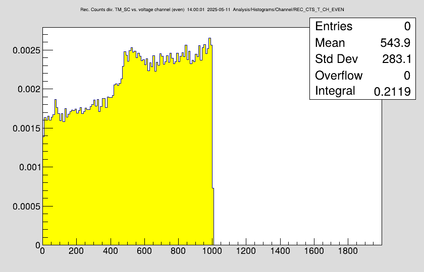
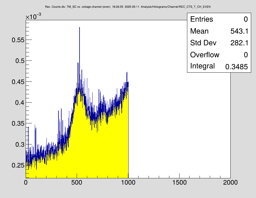
The DR setup was put into operation yesterday and first spectra recorded (see below).
Particle detector behind cooler ("SA_SZ") presently has voltage of 1350. The threshold at the CAEN CFD was set to 100 and changed to 150 today. There is a huge gap between noise and signal, however, today it seemed in DR that we had a burst of higher pulses.
Position is -45
Drifttube cooling first was tested with 200 mA.
The Cathode voltage of the cooler is therefore 905V higher than the actual cooling energy. The value measured with the precision HV probe is 205970 V
This is compensated by a -900V at the drifttube to decelerate the electrons.
A ramp is created: 208Bi01.dat that scans the CM energy range from 21 eV to 11 eV where the Bi79+ (1s2 2p_1/2 n=20) DR resonance is located. 1001 steps DEcm = 0.01 eV. Scanning direction high to low.
Times 40 ms measurement, 40 ms cooling ,
SubTrigs:
1 : 5000
2: 8200
3: 8400
4: 8600
Schottky files are recorded on NTCAP:
NTCAP 2025-05-10_19-09-35 (10 injections first 2 injections missing in NTCAP)
Bunched 200mA, run6.lmd, run7.lmd, run9.lmd (run8.lmd is empty).
First DR Peaks visible
Bunched 500 mA (new range) 24 to 4 eV stepwidth 0.02 eV high to low
NTCAP 2025-05-11_13-19-38, run10.lmd
run12.lmd (figure of DR peak attached, please note low channels are high energies)
not Bunched 500 mA, run11.lmd
run12.lmd (figure of DR peak attached, please note low channels are high energies)
run13.lmd is empty
19:10 changed the Go4 code
The measurements with bunched beam should be repeated. |
| Attachment 1: DR_500mA_bunched.png
|
|
| Attachment 2: DR_500mA_DC_long_ramp.png
|
|
|
38
|
Sun May 11 17:30:24 2025 |
Carsten, Rodolfo, Jonas | General | Accidentally Skipped Breeding Step in File 0012.LMD |
At ~17:26:30 the beam process was accidentally set to not wait on breeding, affecting the data in file 0012.LMD |
|
39
|
Sun May 11 20:08:37 2025 |
Carsten | Runs | DR runs with DC beam |
We have 4 valid DR files for DR with unbunched beam. Iel = 500mA
run_0011.lmd
run_0012.lmd
run_0014.lmd
run_0015.lmd
corresponding ADC data for the DT voltages are available (ESR NUC).

NTCAP is stopped at ~22:30
(Plan: go back to bunched beam)

Below is a first offline analysis of the DR data of and of the intermediate cooling step (-900V) of unbunched beam.
The DR spectrum goes from Ecm = 24eV (channel 1) to 4 eV at channel (channel 1001)  with a stepwidth of 0.02 eV per channel (equidistant in the CM-frame). Thus 100 channels are 2 eV.
The other spectrum shows the intermediate cooling rate after each measurement step.
The maximum of he peak is at about channel 520, i.e 24 eV - 5.2*2eV = 13.6 eV (expected ~17.8 eV). The peak is very broad. FWHM about 100 channels (2 eV). For comparison, the old data from 1998 had FWHM ~0.6 eV but limited due to density of the resonances - not experimental resolution.

The rising slope is the real RR (radiative recombination at non-zero energies) slope. There is no background from residual gas (verified in the bunching spectrum).
The intermediate cooling rate is about 2.5 to 3 times the rates in the DR spectrum. Expected was AT LEAST a factor 10 but rather a factor of 100 (one hundred). This finding is inline with the long beam lifetimes and the moderate breading efficiency.

Comment: In the analysis, I carefully checked all relevant raw-data spectra, in particular the timing pattern and the measured voltages. The raw data look extremely good (from a technical point-of-view)and agree with the settings.
=> The new setup works very well. |
| Attachment 1: DR_500mA_Not_Bunched.png
|
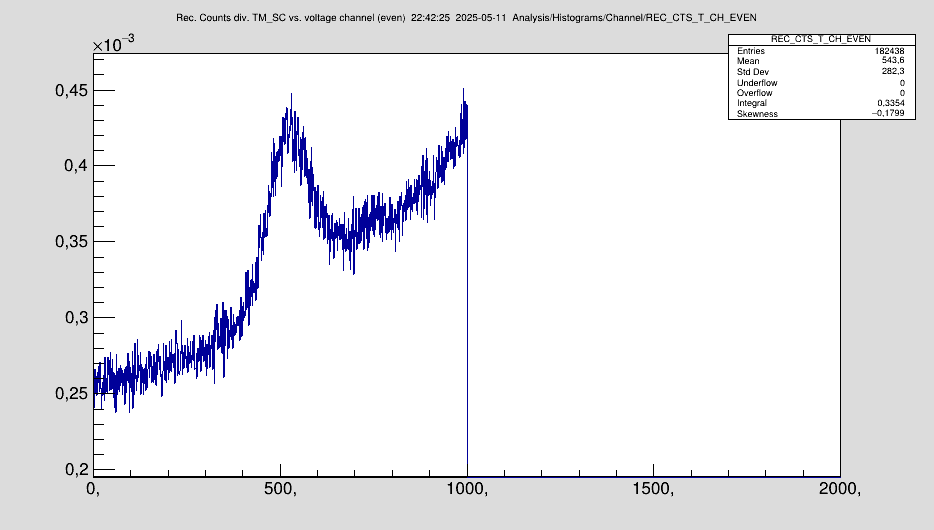
|
| Attachment 2: RR_500mA_Not_buched.png
|
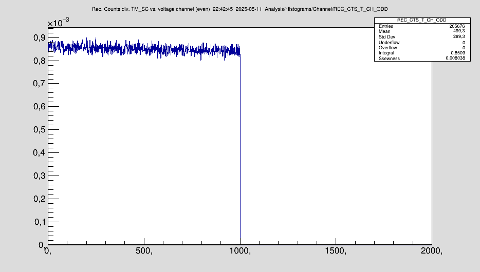
|
|
40
|
Sun May 11 23:16:14 2025 |
Carsten | Runs | Switched back to bunching beam |
At about 22:30 we switched back to the bunched beam.
The new NTCAP directory is IQ_2025-05-11_22-37-04, started NTCAP Schottky data.
Same ramp as before 24 eV to 4 eV. 1001 steps dE = 0.02 eV,
Measurement step 40 ms / cooling step 40 ms.
The ramp is repeated 15 times.
I_el = 500 mA.
Opened file run_0016.lmd
Jonas checked that the bunching works using the scope in the main control room.

The DR peak appears after very few scans. |
|
41
|
Mon May 12 07:19:16 2025 |
Finn, Simon, Konstantin | DAQ | DR Measurements |
During this night we recorded several DR measurements. Before the DR, we charged bread for about 10 minutes.

1. We took over at 0:00 with file no.16 (started 22:15)
2. Started new file (no.17) at 4:34
3. Recorded file no.18 starting at 6:30

We stopped the measurement at 7:28 and started the shut down procedure. |
|
42
|
Mon May 12 10:09:21 2025 |
Christopher, Nils | Accelerator | Intervention TK Chopper - no beam for one hour |
At 11am there will be an intervention for about one hour related to the TK chopper - hence no beam for SIS as well as ESR.
During that time, the pneumatic drives within ESR will be mechanically checked (lubricated).

The ESR-colleagues re-checked the charge states in the ring. |
|
43
|
Mon May 12 14:47:52 2025 |
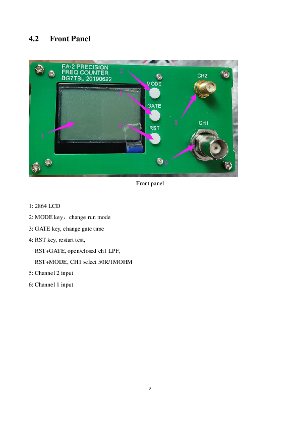
Christopher | DAQ | frequency counter |
FA-2 frequency counter |
| Attachment 1: BG7TBL_FA-2_Frequency_Counter_Operator_Manual-62519_English_Ed.pdf
|


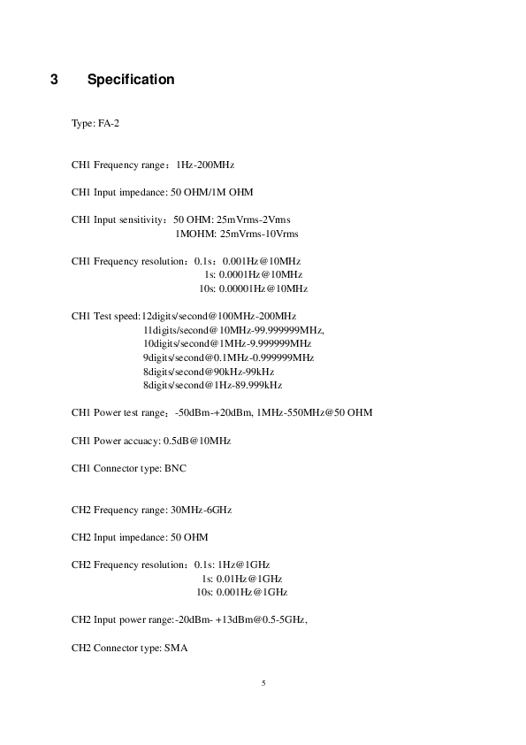
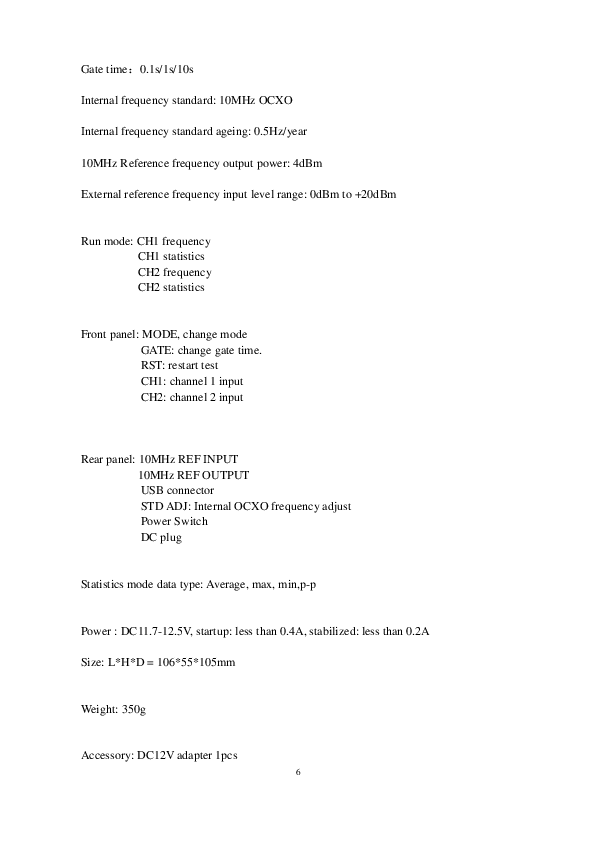
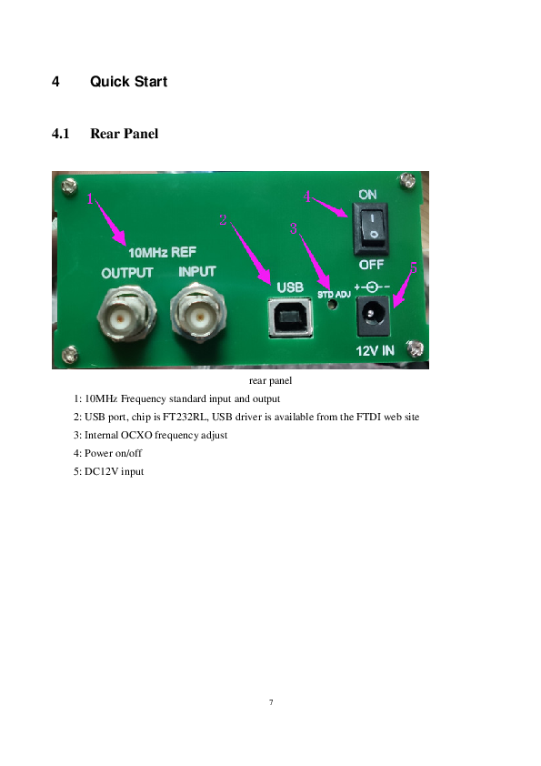
|
|
44
|
Mon May 12 21:39:49 2025 |
Zoran | Runs | DR running again with Bi209 |
Stronger spectra than before, probably due to a stronger overlap with the electron beam.
Open files starting with run_0022, finished with 0025, each one about 6 min charge breeding and 11 min ramp
ntcap stopped, electron current 500 mA, DC beam |
|
45
|
Mon May 12 22:44:00 2025 |
Zoran | Runs | 209Bi bunched beam |
ntcap restarted (05-12_22-22-23), measuring with bunched beam
10 min breeding time |
|
46
|
Mon May 12 23:34:39 2025 |
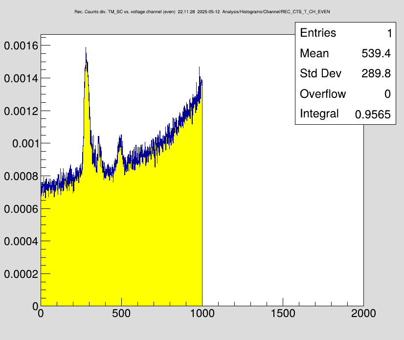
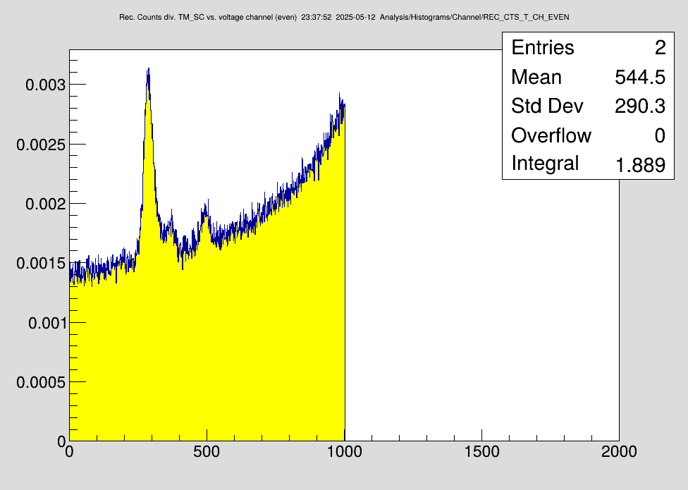
Carsten | Analysis | Sample DR Spectra |
See attachment - electron current 500 mA.
First spectrum DC,
Second spectrum bunched.
Resolution is slightly worse for bunched beam but not dramatically.
Please note, that the ratio DR/RR is 1:1.
Spectra are about 4-5 injection cycles each. (and due to the shorter lifetime with 8 scans instead of 15 scans).
ion beam intensity : about 2e7 Li-like
Other settings as before.

-> Resonance is now at the correct energy! |
| Attachment 1: DR_209Bi_500mA_newESR_settings.png
|
|
| Attachment 2: DR_209Bi_500mA_newESR_settings_bunched.png
|
|
|
47
|
Tue May 13 00:05:39 2025 |
Konstantin | Calibration | Cooler HV |
The DR measurement was repeated with proper electron cooler settings. Readout of electron cooler HV is not affected by the Grafana failure and can be displayed in Medusa in the View "Log-Display". Measured voltages in Subchain 8 are:
- 500mA cooler current, file 25-26 (CR DAQ), NTCAP folder closed
|
Ohmlabs | 205854 | |
PTB 3.2 | 205861 | |
PTB 3.3 | 205862
|
- 250mA cooler current, file no.27 (CR DAQ), NTCAP folder "IQ_2025-05-13_00-18-48"
|
Ohmlabs | 205812 | |
PTB 3.2 | 205819 | |
PTB 3.3 | 205819
|
The cooling energy is 900V lower, since it is compensated by the drift tube HV. |
|
48
|
Tue May 13 00:36:27 2025 |
Finn, Simon, Konstantin | | DR measurements. Night shift. |
|
Time | File | PTB 32 | PTB 33 | Ohmlabs | ESR intensity SC8 | Typical SIS injections | comments | |
00:18 | 27 | 205819 | 205819 | 205812 | 2.24e7 | 4e8 | | |
01:11 | 27 | 205819 | 205820 | 205812 | 2.45e7 | 5e8 | | |
01:40 | 27 | 205818 | 205820 | 205812 | 2.89e7 | 9e8 | ion source cathode changed | |
02:06 | 27 | 205819 | 205820 | 205812 | 3.06e7 | 9e8 | | |
02:33 | 28 | 205819 | 205820 | 205812 | 2.77e7 | 9e8 | opened new file | |
03:00 | 28 | 205819 | 205820 | 205812 | 2.77e7 | 9e8 | detector went too far in and killed the beam | |
03:26 | 29 | 205819 | 205820 | 205813 | 3.03e7 | 9e8 | opened new file | |
? | 29 | 205819 | 205820 | 205813 | 2.84e7 | 7e8 | | |
04:21 | 29 | 205819 | 205820 | 205813 | 2.65e7 | 9e8 | | |
04:45 | 29 | 205819 | 205820 | 205813 | 2.61e7 | 8e8 | | |
05:08 | 30 | 205820 | 205821 | 205813 | 2.63e7 | 9e8 | opened new file | |
05:31 | 30 | 205820 | 205821 | 205813 | 2.63e7 | 8e8 | detector went too far in and killed the beam | |
05:55 | 31 | 205819 | 205820 | 205813 | 2.56e7 | 7e8 | opened new file
|
|
|
49
|
Tue May 13 00:43:31 2025 |
Konstantin | General | Connection interrupt |
Connection reset to all NUCs by accident manual power cut. |
|
50
|
Tue May 13 01:21:16 2025 |
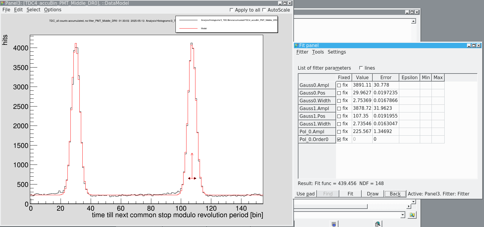
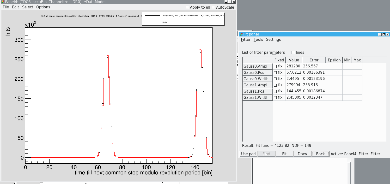
Konstantin, Simon | Analysis | Longitudinal bunch length |
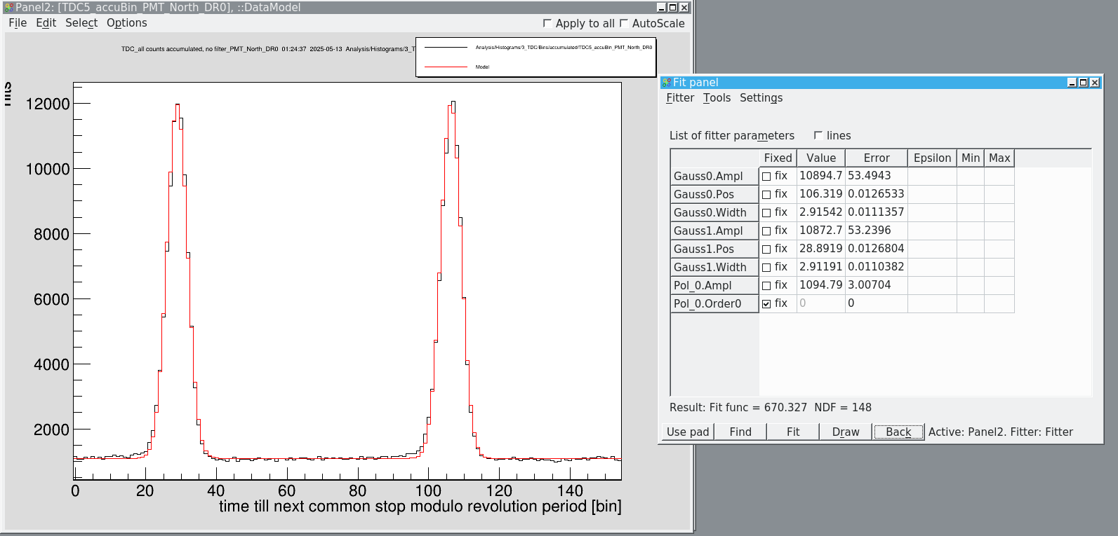
We measured the longitudinal bunch length for all different detectors
|
| PMT north | PMT mid | particle detector
| |
width (bins) | 2.91 | 2.74 | 2.45
| |
width (ns) | 9.60 | 8.98 | 8.09
|
|
| Attachment 1: Bildschirmfoto_2025-05-13_01-24-40.png
|
|
| Attachment 2: Bildschirmfoto_2025-05-13_01-33-06.png
|
|
| Attachment 3: Bildschirmfoto_2025-05-13_01-38-19.png
|
|
|
51
|
Tue May 13 12:59:49 2025 |
Carsten, Wilfried, Christopher, Nils | General | Setup of ESR for 208Bi |
In the morning the colleagues from ESR setup the beam for production of 208Bi81+, however the identification (via the schottky) of the correct fragments and charge states is still ongoing.

Issue with the pneumatic drives (scraper/detector) is still not solved yet, however we want to give it a try with the current limitations unless it becomes absolutely necessary. |
|
52
|
Tue May 13 15:34:23 2025 |
Yuri | Calibration | Particle Identification |
Setting on 208Bi81+
Manipulation after accumulation and orbit shift, before slowing down

f(MHz) - A/Q <<< comment
243.031 - 209/80 <<< primary beam charge state
<<< missing @243.068 - 201/77
<<< missing @243.111 - 206/79
243.191 - 203/78
243.231 - 208Bi80+ ******
243.274 - 200/77
243.314 - 205/79
<<< missing @243.360 - 197/76 <<< probably under the bump of uncooled beam <<< has been seen in another manipulation
<<< missing @243.396 - 202/78 <<< probably under the bump of uncooled beam <<< has been seen in another manipulation
<<< missing @243.431 - 207/80 <<< probably under the bump of uncooled beam <<< has been seen in another manipulation
<<< missing @243.482 - 199/77 <<< probably under the bump of uncooled beam
243.516 - 204/79 <<< a_pi=-0.17
243.549 - 209/81 <<< primary beam charge state
<<< missing @243.604- 201/78
243.634 - 206/80 <<< a_pi=-0.168
243.694 - 198/77
243.721 - 203/79 <<< a_pi=-0.170
243.746 - 208Bi81+ *****
243.784 - 195/76
243.811 - 200/78 <<< a_pi=-0.172
243.836 - 205/80
243.879 - 192/75
243.904 - 197/77
243.926 - 202/79
243.946 - 207/81 << a_po=-0.170 |
|
53
|
Tue May 13 17:46:35 2025 |
Carsten | Runs | Start of DR measurements with 208Bi |
Same ramps as before, 8 repetitions.
ESR is set-up for breeding of 208Bi80+.
In order to reduce unwanted primary at injection to the ESR, in the transfer line scrapers are in use, presently GTE4DS5HL -5.0, GTE4DS5HR +7.0
The 208Bi80+ can be easily scraped since most unwanted species are lost during the deceleration ramp, and only 3 peaks remain. These 3 peaks are quite far away from the 208Bi80+.
Please note, that frequencies at decelerated beam is different than the ones in Yury's ID.
The detector DD1AG is not moving.
For scraping essentially DS3HG and DD1IG are used plus the particle detector.
DS3HG also shows the "overshooting behavior of DD2_G (particle detector, but not so strong).
Scraping of the 208Bi80+ with DS3HG at 0 but at -35 alreadz all other peaks are gone, thus the setting for the scraper DD3_DS3HG is -35.
With the DD1IG we cannot touch the 208Bi80+. Set to 26.
Particle detector presently is at -65 but this might be too far out.
I_el is 500mA, NOT bunched for the first tests.
stopped and restarted NTCAP: IQ_2025-05-13_17-39-30
run032.lmd (detector position not very good).
We had about 1e6 ions at the low energy.
First DR spectrum of 208Bi80+ but with moderate statistics. Going to different detector position as cross check.
18:05 closed run0032.lmd
Changed detector position to from -65 to -55.
Opened file from run0033.lmd
(At the moment 10 injections, 60 x 10s waiting - 10 min)
Intensity is about 1e6 ions at the beginning of the measurement.
After a few scans we see the first DR spectrum of 208Bi80+
Thus, we are sure to have the right beam.
Resolution is good.
The attached (online) spectrum is about 4 or 5 fully cycles (>1 h).
Please keep in mind that these are "small" DR resonances.
The lower spectrum is about 60% of the true counts during this time. |
| Attachment 1: DR_208Bi_500mA_unbunched(DC).png
|
.png.png)
|
| Attachment 2: DR_208Bi_500mA_unbunched(DC)_true_counts.png
|
_true_counts.png.png)
|
|
54
|
Tue May 13 21:37:09 2025 |
Carsten | Runs | DR run with bunched beam / 500 mA /208Bi80+ |
Just changed settings towards a new scanning range and bunched beam.
Stopped and started NTCAP, now: IQ_2025-05-13_21-01-44
new ADC file
NEW ENERGY RANGE AND TIMING
Scan from 21 eV to 11 eV with 1001 steps and Delta E = 0.01 eV
8 repetitions
SubTriggerTiming:
5800
10200
10400
10600
200
200
200
500 mA / bunched beam; other settings as before
run0035.lmd opened
Please note that the peak now looks differently, in particular in looks broader (dE = 0.01ev instead of dE =0.02 eV))and is at a different position |
|
55
|
Wed May 14 00:11:52 2025 |
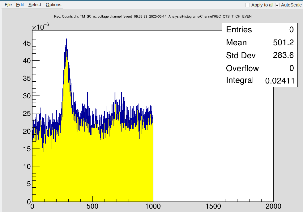
Dimitrios, Simon | Runs | Night shift DR Bi-208 |
|
Time | File | PTB 32 | PTB 33 | Ohmlabs | ESR intensity SC8 | Typical SIS injections | comments | |
00:15 | 36 | 205860 | 205861 | 205853 | 0 | 8e8 | something killed the beam after deceleration, particle detectors look fine | |
00:42 | 37 | 205860 | 205861 | 205853 | 5e5 | 7e8 | opened new file | |
01:09 | 37 | 205860 | 205861 | 205853 | 5e5 | 7e8 | | |
01:38 | 37 | 205860 | 205861 | 205853 | 5e5 | 8e8 | | |
02:04 | 37 | 205861 | 205862 | 205854 | 4e5 | 5e8 | | |
02:31 | 38 | 205861 | 205862 | 205854 | 4e5 | 6e8 | opened new file | |
02:56 | 38 | 205861 | 205862 | 205854 | 4e5 | 6e8 | | |
03:23 | 38 | 205861 | 205862 | 205854 | 4e5 | 6e8 | | |
03:51 | 38 | 205860 | 205861 | 205854 | 6e5 | 5e8 | | |
04:15 | 39 | 205860 | 205861 | 205854 | 5e5 | 5e8 | opened new file | |
04:40 | 39 | 205860 | 205861 | 205854 | 4e5 | 5e8 | | |
05:08 | 39 | 205860 | 205861 | 205854 | 4e5 | 5e8 | | |
05:34 | 39 | 205860 | 205861 | 205854 | 3e5 | 5e8 | | |
06:00 | 40 | 205860 | 205861 | 205854 | 4e5 | 4e8 | opened new file | |
06:29 | 40 | 205860 | 205861 | 205854 | 0 | 4e8 | particle detector went too far in and killed the beam
|
|
| Attachment 1: Screenshot_2025-05-14_06-33-45.png
|
|
|
56
|
Wed May 14 02:19:46 2025 |
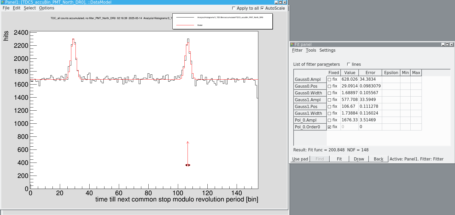
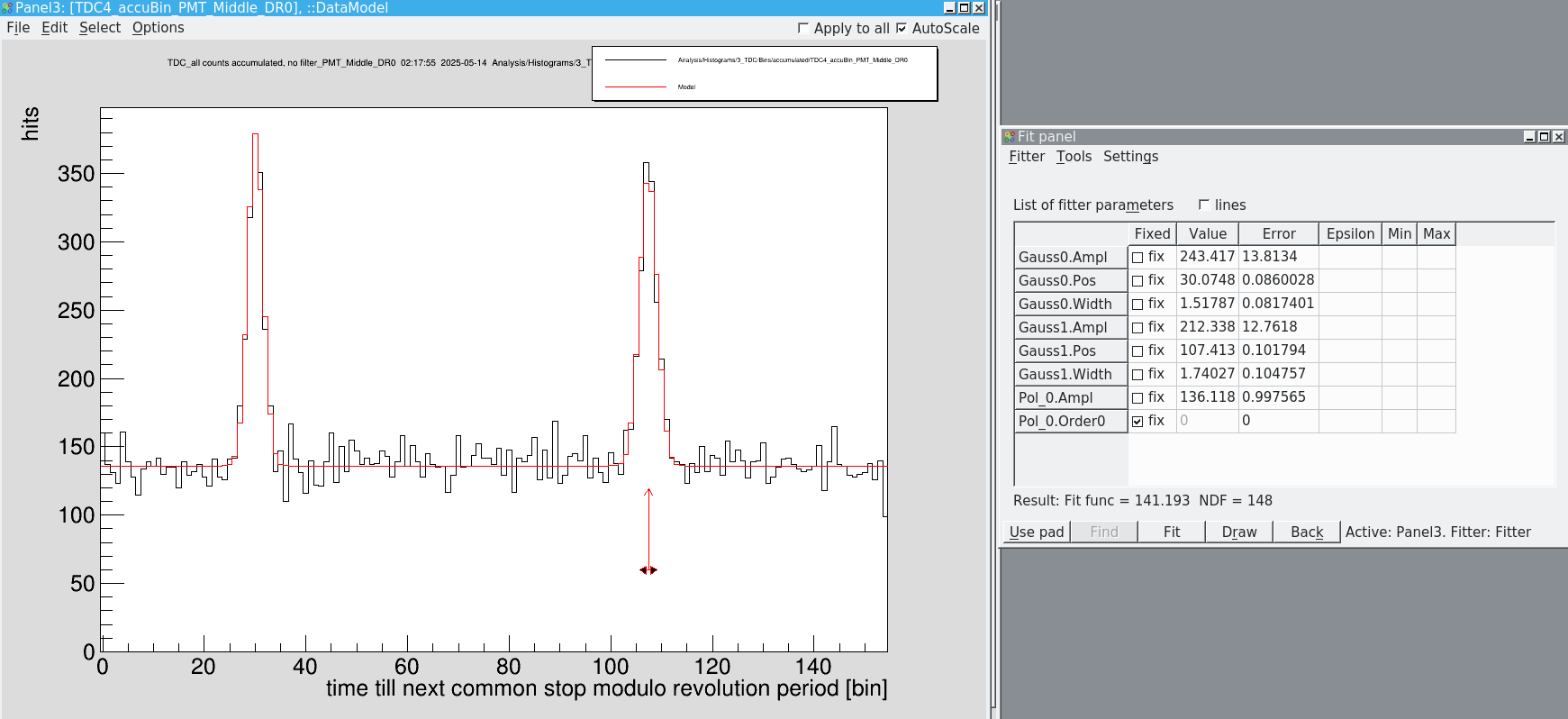
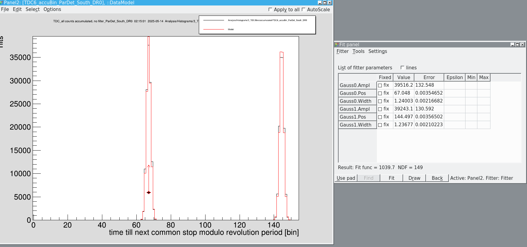
Dimitrios, Simon | Analysis | Longitudinal bunch length |
We repeated this measurement for 208-Bi. The bunch lengths are about half as long (due to lower space charge and consequently less heating?)
|
| PMT north | PMT mid | particle detector
| |
width (bins) | 1.7 | 1.6 | 1.24
| |
width (ns) | 5.6 | 5.3 | 4.09
|
| Quote: | We measured the longitudinal bunch length for all different detectors
|
| PMT north | PMT mid | particle detector
| |
width (bins) | 2.91 | 2.74 | 2.45
| |
width (ns) | 9.60 | 8.98 | 8.09
|
|
|
| Attachment 1: Bildschirmfoto_2025-05-14_02-16-42.png
|
|
| Attachment 2: Bildschirmfoto_2025-05-14_02-17-58.png
|
|
| Attachment 3: Bildschirmfoto_2025-05-14_02-15-05.png
|
|
|
57
|
Wed May 14 06:31:28 2025 |
Dimitrios, Simon | Runs | DR scans @300mA |
We reduced the electron cooler current to 300mA and continued measuring the DR spectrum.
|
Time | File | PTB 32 | PTB 33 | Ohmlabs | ESR intensity SC8 | Typical SIS injections | comments | |
6:56 | 41 | 205826 | 205827 | 205819 | 5e5 | 4e8 | opened new file | |
7:23 | 41 | 205826 | 205827 | 205820 | 5e5 | 6e8 | | |
7:48 | 41 | 205826 | 205827 | 205820 | 5e5 | 5e8 | | |
8:16 | 41 | 205826 | 205827 | 205820 | 0 | 4e8 | the beam was killed, could be by GE02DS3HG, although it did not go in too far | -
|
|
|
58
|
Wed May 14 08:24:39 2025 |
Danyal, Nils, Hendrik Day shift | Runs | DR scans @300mA |
Continuing with the measurements of the last shift, also at 300mA. Creating new file, as beam got killed during last run.
|
Time | File | PTB 32 | PTB 33 | Ohmlabs | ESR intensity SC8 | Typical SIS injections | comments | |
8:42 | 42 | 205826 | 205827 | 205820 | 4e5 | 4e8 | opened new file | |
9:07 | 42 | 205826 | 205827 | 205820 | 4e5 | 4e8 | | |
9:34 | 42 | 205826 | 205827 | 205820 | 3e5 | 4e8 | | |
9:59 | 42 | 205826 | 205827 | 205820 | 0 | 4e8 | DS3HG went to position 20.4, killing the beam | |
10:24 | 43 | 205826 | 205827 | 205820 | 3e5 | 4e8 | opened new file | |
10:51 | 43 | 205826 | 205827 | 205820 | 0 | 4e8 | Beam in the ESR got killed again. DS3HG is at normal position though, so we don't know why | |
11:17 | 44 | 205826 | 205827 | 205820 | 0 | 4e8 | opened new file, DS3HG killed the beam again | |
11:41 | 45 | 205826 | 205827 | 205820 | 2e5 | 4e8 | opened new file | |
12:07 | 45 | 205826 | 205827 | 205820 | 0 | 4e8 | DS3HG killed the beam by going too far for just a second and then going to normal position. Maybe that was the reason some previous
beams got killed even though when we looked at the scraper it was in the normal position | |
11:41 | 46 | 205826 | 205827 | 205820 | 2e5 | 4e8 | opened fie | |
|
|
|
59
|
Wed May 14 11:59:39 2025 |
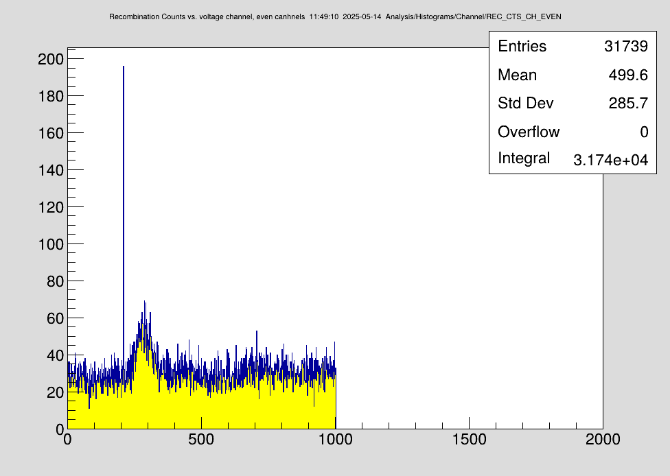
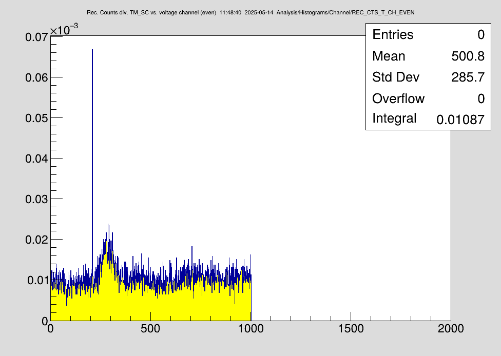
Nils | Analysis | Current DR spectra 208Bi |
Results so far for the DR scans @300mA e-cooler current. |
| Attachment 1: DR_208Bi_300mA_raw.png
|
|
| Attachment 2: DR_208Bi_300mA_Time_normalized_.png
|
|
|
60
|
Wed May 14 12:43:43 2025 |
Danyal, Nils, Hendrik Day shift | Runs | DR scans @300mA |
Continuing with the measurements of the last shift, also at 300mA. Creating new file, as beam got killed during last run.

[TABLE border="1"]
Time |File | PTB 32 | PTB 33 | Ohmlabs | ESR intensity SC8 | Typical SIS injections | comments |-
8:42 | 42 | 205826 | 205827 | 205820 | 4e5 | 4e8 | opened new file |-
9:07 | 42 | 205826 | 205827 | 205820 | 4e5 | 4e8 |-|-
9:34 | 42 | 205826 | 205827 | 205820 | 3e5 | 4e8 |-|-
9:59 | 42 | 205826 | 205827 | 205820 | 0 | 4e8 | DS3HG went to  position 20.4, killing the beam |-
10:24 | 43 | 205826 | 205827 | 205820 | 3e5 | 4e8 | opened new file |-
10:51 | 43 | 205826 | 205827 | 205820 | 0 | 4e8 | Beam in the ESR got killed again. DS3HG is at normal position though, so we don't know why |-
11:17 | 44 | 205826 | 205827 | 205820 | 0 | 4e8 | opened new file, DS3HG killed the beam again |-
11:41 | 45 | 205826 | 205827 | 205820 | 2e5 | 4e8 | opened new file |-
12:07 | 45 | 205826 | 205827 | 205820 | 0 | 4e8 | DS3HG killed the beam by going too far for just a second and then going to normal position. Maybe that was the reason some previous beams got killed even though when we looked at the scraper it was in the normal position. Stopped measurements so Sergey can maybe fix the issue with the scraper. Slightly adjusting the setpoints of the scraper should fix the problem of it going too far. Last file got closed. |-
[/TABLE] |
|
61
|
Wed May 14 19:06:51 2025 |
Carsten | Runs | Different pattern/ Fixes during the day new runs for 300 mA (increased intensities) |
During the day several things were discussed concerning intensity and the pressurized air devicees.
In total 6 to 7 different things are not ok for a proper opreation of the devices (not to be discussed here).
As a workaround on top of other workarounds:
We now have a different pattern with dedicated subchains for moving detector (+ additional possibilities for manipulations that might become handy)
- Detectors are moved in in SC9 and out in SC12. Due to the 3 internal beam processes (BP1 to BP3) the old SC7 was not suited for that.
- The waiting machine for measurements is now SC10
- The ranp file has now a 5 seconds waiting at the beginning to compensate for the longer time between ramping down and scraping.
- As a byproduct the deceleration decomes more efficient.
- Since the detector north 02DD2AG seems to drivemore reliable than the scraper 02DS3HG we now use the detecotr north for scraping.
- Positions in SC9: 01DD2AG: -55 (destroys beam at ~-25); 01DD1AG: 26; 02DD2_G: -60, all out positions (SC12) are 120 (-120)
- Due to the higher number of beam processes, changes of electron current or the delta voltage have to be performed in both, SC8 and SC10.
- The first 10 channels or so in the DR spectra might show some weird behaviour - don't worry that is "by design" (aka due to the changes above).
- We now had 2e6 208Bi80+ for 8e8 SIS current (15 injections, 45 cycles breeding at 10s) - thre still seems to be some headroom.
NTCAP: 2025-05-14_18-47-20
300mA (bunched) , delta U = 880V (-20V without drifttube cooling)
run 0047.lmd started (at least 0046.lmd is empty, check also teh other files sincve the morning shift).
Further files for 300 mA: 0048.lmd und 0049.lmd
Typical ion beam intensities at beginning of scan: up to 3e6 scraped
Spectra below.
The optimal channels for DRALS would be 290 (max.) (F=4) that is shifted for the F=5 by 878 eV (+88 channels) to channel 378. Here the max of the pure HFS excited resonances would appear.
This translates into lab energy voltages of 3348V (F=4 maximum) and 3243 V (F=5 maximum) and -900V cooling.
These voltages are only valid for 300 mA. Voltages for 500mA are very similar (offline analysis). For practical purposes, the same voltages can be used for 300 mA bunched and 500 mA bunched.
Closed NTCAP file |
| Attachment 1: DR_208Bi_300mA_optimized_ion_beam.png
|
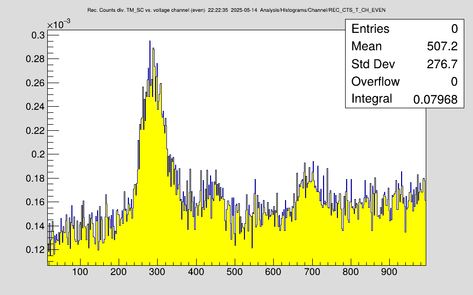
|
| Attachment 2: DR_208Bi_300mA_optimized_ion_beam_cts.png
|
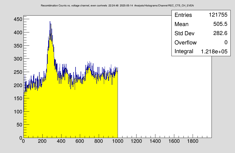
|
|
62
|
Wed May 14 22:05:54 2025 |
Rodolfo | Laser | Laser settings |
Here are summarized some settings of the laser system.
Dye: Pyrromethene 597 in Ethanol
- Concentration Resonator: 0.16 g/l
- Concentration Amplifier: 0,02 g/l
Seeding Energy: 350 mJ @ 532 nm.
Output Energy: 150 mJ @ 593 nm.
Laser linewidth: 6 GHz (Expansion factor 10x) |
|
63
|
Thu May 15 00:45:19 2025 |
Carsten | DAQ | DRALS preliminary timing settings (DR part) |
DAC control on sadpc115
- Total measurement window: 600 001 ms (10 min + 1ms)
- COOL: 16800 us
- MEAS0 / MEAS1 : 16800us
- Ramp phase delay: 3000 us
- Voltage MEAS0 (MAX of F=4 Peak) : 3348V
- Voltage MEAS1 (MAX of F=4 Peak) : 3243V
- Voltage COOL: -900V
SubTriggers
[1] 5500 us
[2] 2000 us
[3] 2200 us
[4] 2400 us
[5] 200 us (not connected)
[6] 200 us (not connected)
[7] 200 us (not connected)
|
|
64
|
Thu May 15 02:14:17 2025 |
Rodolfo, Konstantin, Simon | Laser | Laser broken |
The pump laser is broken!

To be more specific the YAG crystal looks cracked (see att.) and we don't have a spare one.
First thing tomorrow morning we will call InnoLas and ask if they can repair it before the weekend.
If not, Rodolfo will install the old Quanta Ray laser for the remaining beamtime. |
| Attachment 1: IMG_1716.jpg
|
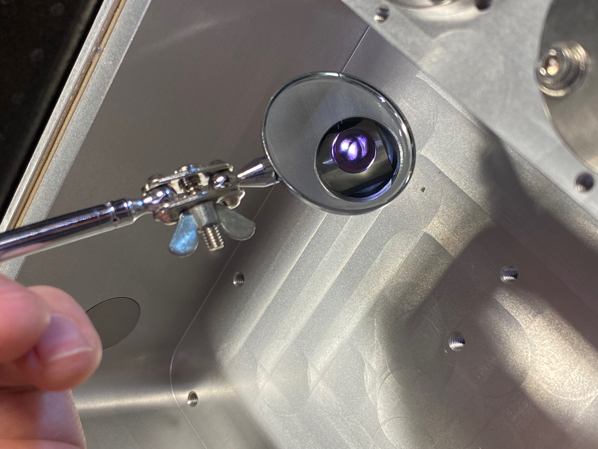
|
|
65
|
Thu May 15 02:34:30 2025 |
Dimitrios, Konstantin, Simon | Accelerator | Ion beam position |
We measured the ion beam position with the T-scrapers. Not that the blades are 8mm wide, which must be considered to calculate the central beam position where the laser must be aligned to.
|
motor | ion beam position (mm) from outside | ion beam position (mm) from inside | central beam position (mm) | |
DS1VU (GECEDS1VU) | 0.5 | - | 4.5 | |
DS1HA (GECEDS1HA) | -4.5 | -12.5 | -8.5 | |
DS2VU (GECEDS2VU) | 0.5 | - | 4.5 | |
DS2HA (GECEDS2HA) | -1.5 | -10 | -5.75
|
|
|
66
|
Thu May 15 13:40:47 2025 |
Carsten | Runs | DR run DC with 300mA and very fine stepwidth |
Just changed settings towards a new scanning range and bunched beam.
NTCAP, now: IQ_2025-05-15_12-00-29
new ADC file
NEW ENERGY RANGE
Scan from 21 eV to 11 eV with 4001 steps and Delta E = 0.025 eV
3 repetitions (first run 4)
SubTriggerTiming:
5800
10200
10400
10600
200
200
200
300 mA / DC beam;
run0051.lmd opened
14:25 closed file 51
Changed to 2 repetitions
opened file 0052.lmd
15:46 clsoed file 0052.lmd - in the last injection the ramp was not started (DAC was clamped)
file 0053.lmd/ 0054 / 0055 must not be used.
File 0056 higher intensities timing optimizations - don't trust the first 200 channels.
File 0056 end (last injection) SC not stopped - beam destroyed.
19:19: Opened File 0057.lmd
New NTCAP directory: IQ_2025-05-15_19-00-41
File 0058.lmd running with multiturn injection in SIS.
At end of file 0058 injections (forgot to stop SC)
opened and closed file 0059 (good data)
Stopped NTCAP.
Preparations for HV calibration with DC beam. |
|
67
|
Fri May 16 03:19:23 2025 |
Dimitrios, Finn, Konstantin | Accelerator | Changed settings to DRALS setup |
Switched to bunching: Ring HF Bucket_fill(RF_manipulation)(SC7,BP2) changed from [3.0, 0.0] -> [3.0, 3.0]
Injections 5 | Breeding 30 |
|
68
|
Fri May 16 03:22:05 2025 |
Carsten, Dimitrios, Konstantin | Calibration | DR scan and HV Calibration against Schottky frequency (NTCAP) |
DR scan and HV Calibration against Schottky frequency (NTCAP).
Since DR measurements are presently running with DC beam we can easily do a calibration of cooler voltage against Schottky frequency at the end of the DR scan.

When the DR scan is finished, the beam is dragged to the 900V too high cooler voltage.

In manipulation machine we change the cooler voltage in steps of 100 V and measure it. The according Schottky data of the single line are in the NTCAP directory: IQ_2025-05-15_23-46-52 (IQ_2025-05-16_00-26-37)
DR run file run0060.lmd

We do 20 injections, and 75 times 10s cooling/breeding

In the end we measured the revolution frequency as a function of the correction in the electron cooler HV GECEBG1E (Delta Uacc) Paramodi folder ESR Manipulation


all values at I_el = 300mA
[TABLE border="1"]
Voltage correction | PTB 3.2 / V | PTB 3.3 / V | Ohmlabs / V| Revolution frequency / MHz |-
 880 | 205826 | 205827 | 205820 | 1,940625 |-
 980 | 205926 | 205927 | 205919 |  |-
 880 | 205826 | 205827 | 205820 | 1,940625 |-
 780 | 205727 | 205927 | 205919 |  |-
 680 | 205626 | 205927 | 205919 |  |-
 580 | 205527 | 205927 | 205919 |  |-
 480 | 205427 | 205927 | 205919 |  |-
 380 | 205326 | 205927 | 205919 |  |-
 280 | 205226 | 205927 | 205919 |  |-
 180 | 205126 | 205927 | 205919 |  |-
 080 | 205026 | 205927 | 205919 |  |-
 -20 | 204926 | 205927 | 205919 |  |-
-120 | 204826 | 205927 | 205919 |

[/TABLE]

[TABLE border="1"]
Voltage correction | PTB 3.2 / V | I_el / mA |-
-20 | 204910 | 200 |-
-20 | 204893 | 100 |-
-20 | 204909 | 200 |-
-20 | 204926 | 300 |-
-20 | 204942 | 400 |-
-20 | 204959 | 500 |-
-20 | 204926 | 300

[/TABLE]

Move back to standard settings
Voltage correction = 880V | PTB 3.2 = 205826V | I_el = 300mA

1:27 NTCAP stop close file |
|
70
|
Fri May 16 04:56:51 2025 |
Finn, Konstantin, Dimitrios | Runs | Night shift DR runs |
We conducted some more DR runes in this night shift at I_el = 300mA:
|
Time | File | PTB 32 | PTB 33 | Ohmlabs | ESR intensity SC8 | Typical SIS injections | comments | |
? | 62 | 205826 | 205827 | 205819 | 3e6 | 2e9 | opened new file | |
? | 62 | 205826 | 205827 | 205820 | 3e6 | 2e9 | | |
4:50 | 62 | 205826 | 205827 | 205820 | 2e6 | 2e9 | | |
5:17 | 62 | 205826 | 205827 | 205820 | 1e6 | 2e9 | | |
5:52 | 62 | 205826 | 205827 | 205820 | 1e6 | 2e9 | | |
6:25 | 62 | 205826 | 205827 | 205820 | 1e6 | 2e9 | | |
6:58 | 62 | 205826 | 205827 | 205820 | 1e6 | 2e9 | | |
7:32 | 62 | 205826 | 205827 | 205820 | 1e6 | 2e9 | | |
|
Closed file |
|
71
|
Fri May 16 08:01:27 2025 |
Finn, Konstantin, Dimitrios | Detectors | Schottky channels |
1kHz read out trigger NTCAP

DC Trafo --> B1 SRC1
U Cooler --> B1 SRC3
I Cooler --> B1 SRC4
P Gun --> B1 SRC5 |
|
72
|
Fri May 16 08:19:00 2025 |
Danyal, Christopher, Hendrik | Runs | morning shift DR runs |
We are continuing taking more DR runes in the morning shift at I_el = 300mA:
opened new file
|
Time | File | PTB 32 | PTB 33 | Ohmlabs | ESR intensity SC8 | Typical SIS injections | comments | |
8:07 | 63 | 205826 | 205827 | 205820 | 0 | 1.5e9 | at about 8:30 the beam was destroyed by a scraper, failure in SIS18 at 8:40 (RF cavity) | |
9:40 | 64 | 205826 | 205827 | 205820 | 1e6 | 1.3e9 | opened new file, at about 9:17 the SIS provided beam again, all looks good | |
10:14 | 64 | 205826 | 205827 | 205820 | 7e5 | 1.3e9 | Voltages have not been read out as the read-out is not active | |
10:47 | 64 | - | - | - | 5e5 | 1.3e9 | same with the voltages as above | |
11:24 | 64 | - | - | - | 4e5 | 1.3e9 | same with the voltages as above, SIS cavity (same as earlier today) had problems and about a third of the injections did not come. For us the beam in the ESR was intense enough for a measurement though. ESR intensity after scraping decreases in the last few measurements but before scraping it is roughly the same. | |
11:58 | 64 | 205821 | 205828 | 205821 | 5e5 | 1.5e9 | voltages read from Grafana interface | |
12:32 | 64 | 205821 | 205828 | 205821 | 5e5 | 1.5e9 | voltages read from Grafana interface. Closed file after measurement and halted measurement to maybe get more beam into ESR. | |
|
|
|
73
|
Fri May 16 11:09:38 2025 |
Danyal, Christopher | Laser | laser damage |
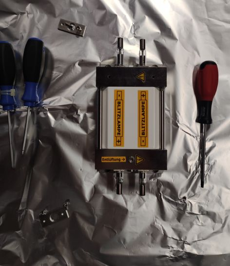
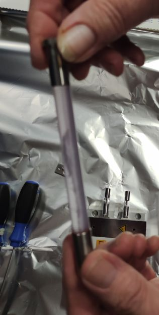
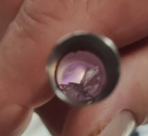
| here are some pictures of the laser damage
The Innolas technician is here now.
The new crystal has arrived (Wilfried just delivered it).
The old crystal broke because of overheating. |
| Attachment 1: No_1.jpg
|
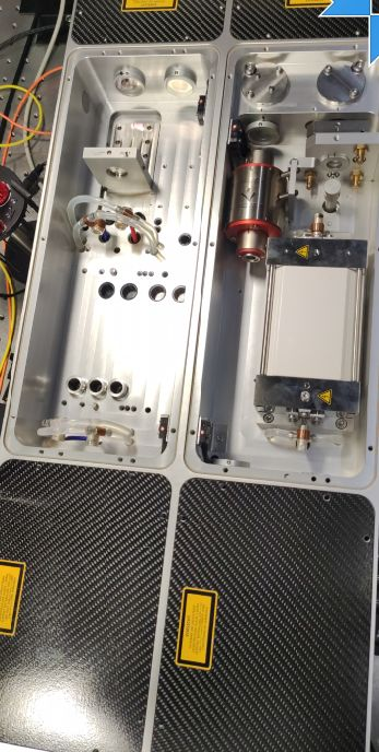
|
| Attachment 2: No_2.jpg
|
|
| Attachment 3: No_3.jpg
|
|
| Attachment 4: No_4.jpg
|
|
|
74
|
Fri May 16 15:25:54 2025 |
Rodolfo, Christopher | Laser | Pumplaser |
The pump laser is back into the operation.
Output energy @ 532 nm: 690 mJ
RMS Stability: 1.45 %
PTP Stability: 10%
500 laser shots average. |
|
75
|
Fri May 16 18:37:32 2025 |
Rodolfo, Carsten, Wilfried, Zoran, Ragandeep, Nils | Laser | Timing |
After some minor adjustments for the laser done by Rodolfo, the laser is back
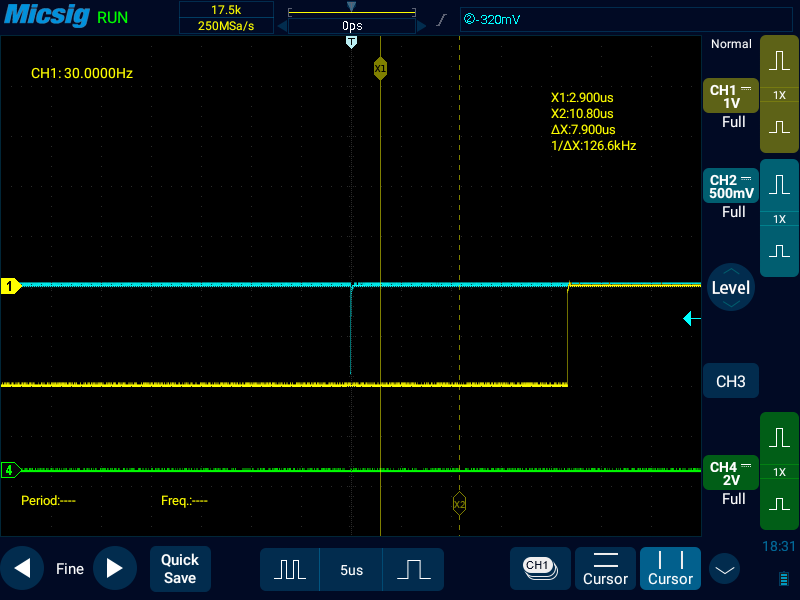
at ESR and visible by the PD-SO.
We checked the timing between the cooling signal of the e-cooler and the
signal produced of the PD-SO, which is suppose to be at the end of the
cooling ramp - seems to work as expected. Picture is attached.

Note added (Carsten): The "cool" signal is generated by the microcontroller. It
is only in sync if the laser signal is put on the input line to the microcontroller.
Otherwise both have independent clocks. |
| Attachment 1: Screenshot_2025-05-16-18-31-35.png
|
|
|
76
|
Fri May 16 19:22:43 2025 |
Carsten | DAQ | New vlaues for DRALS |
The Timing for DRALS has changed to a 12 min measurement window (max time for laser scan). The duration of the laser ramp planned to be 10 min. So we have 2 mins to openfile / closefile etc.
DRALS settings
Measurement Window (Voltage Ramp): 720 001 ms (12 mins + 1000us)
Cooling Window: 16800 us
MEAS0/MEAS1: 16800us
Phase delay (Time for the change of the voltage): 3000us
Voltage Cool: -900V
Voltage Meas0: 3243V (min peak)
Voltage Meas1: 3243V (min peak)
Subtriggers
1: 5500
2: 2000
3: 2200
4: 2400
5: 200 (not wired, but number is needed internally)
6: 200 (not wired, but number is needed internally)
7: 200 (not wired, but number is needed internally)
The voltage on the maximum of the main DR-Peak would be 3348V.
The trigger pattern for the DAQ is running all the time (also during injection) if DRALS mode is ACTIVE (toggle with 511)
In order to avoid the start of the voltages, please use GENESYS (IO3) to set the starting trigger pulse inactive.
DRIFTTUBE Cooling requires cooler settings in ParaModi / ESR Manipulation / deltaUacc in SC 10 = 880 V (SC 8 will be changed automatically).
without drifttube ramping (no trigger) the value is -20 V
An NTCAP file was opened before the tests and during the scraping: 2025-05-16_18-43-02. |
|
77
|
Fri May 16 21:23:44 2025 |
Ragandeep, Rodolfo, Zoran, Nils | Accelerator | Ion and laser beam position |
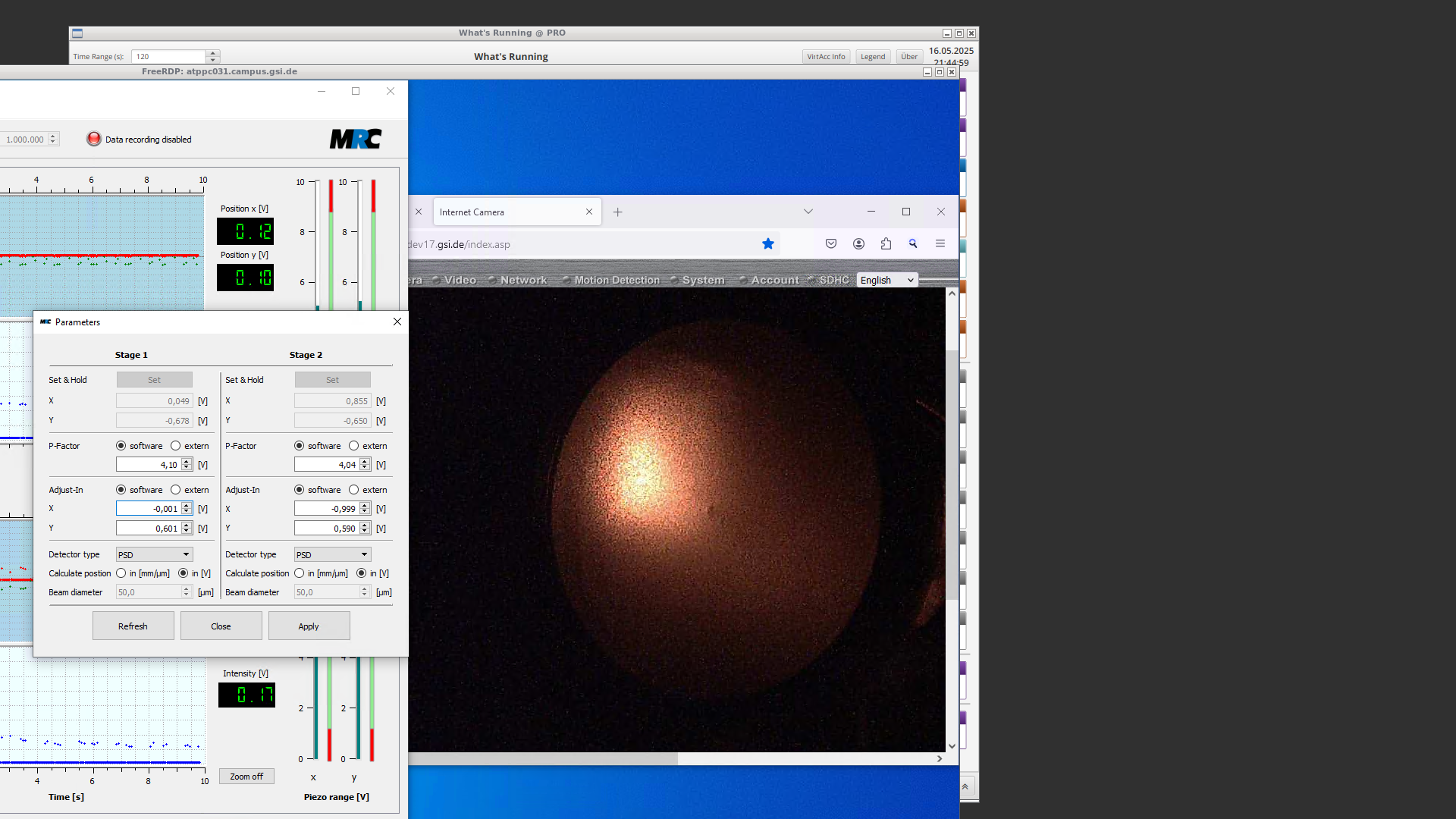
We checked the ion beam position as well as the laser position with the two scraper in front (north) of the e-cooler (GECEDS1VU, GECEDS1HA) and after (south) the e-cooler (GECEDS2VU, GECEDS2HA). The values for the ion beam slightly changed in comparsion to the mesasurment performed in ELOG 65.
|
motor | ion beam position (mm) from outside | ion beam position (mm) from inside | central beam position (mm) | |
DS1VU(GECEDS1VU) | -1.0 | - | 3.0 | |
DS1HA(GECEDS1HA) | -13.5 | -4.0 | -8.5 | |
DS2VU(GECEDS2VU) | 0.0 | - | 4.0 | |
DS2HA(GECEDS2HA) | -11.0 | -1.0 | -5.5
|
The values for the laser position (within MRC) are given in the attached picture. The values we started from are
|
| Stage 1 | Stage 2 | |
x | -0.050 | -0.800 | |
y | 0.601 | 0.602
|
|
| Attachment 1: screenshot-2025-05-16_21-44-5912125648191471033043.png
|
|
|
79
|
Fri May 16 22:15:33 2025 |
Ragandeep, Rodolfo, Zoran, Nils | Laser | Scan range laser |
The scan range according to Wilfried should be

593.15 nm - 592.55 nm

with the resonance at 592.85 nm |
|
80
|
Fri May 16 22:50:00 2025 |
Ragandeep, Rodolfo, Zoran, Konstantin, Nils | Laser | Timing Laser + Ion |
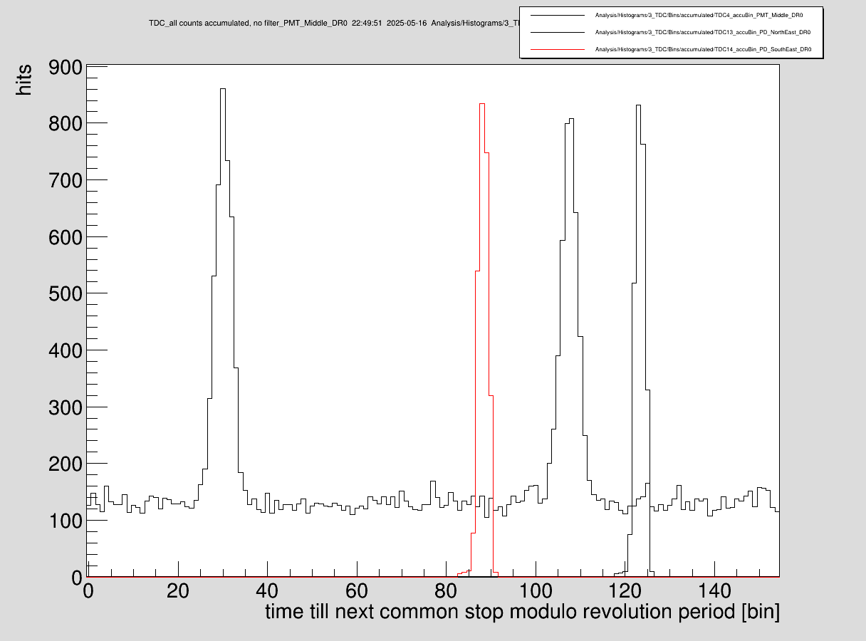
We adjusted the delay of the laser according to the signal of the PD and the PMTs. |
| Attachment 1: Timing_208_DRALS.png
|
|
|
81
|
Fri May 16 22:55:36 2025 |
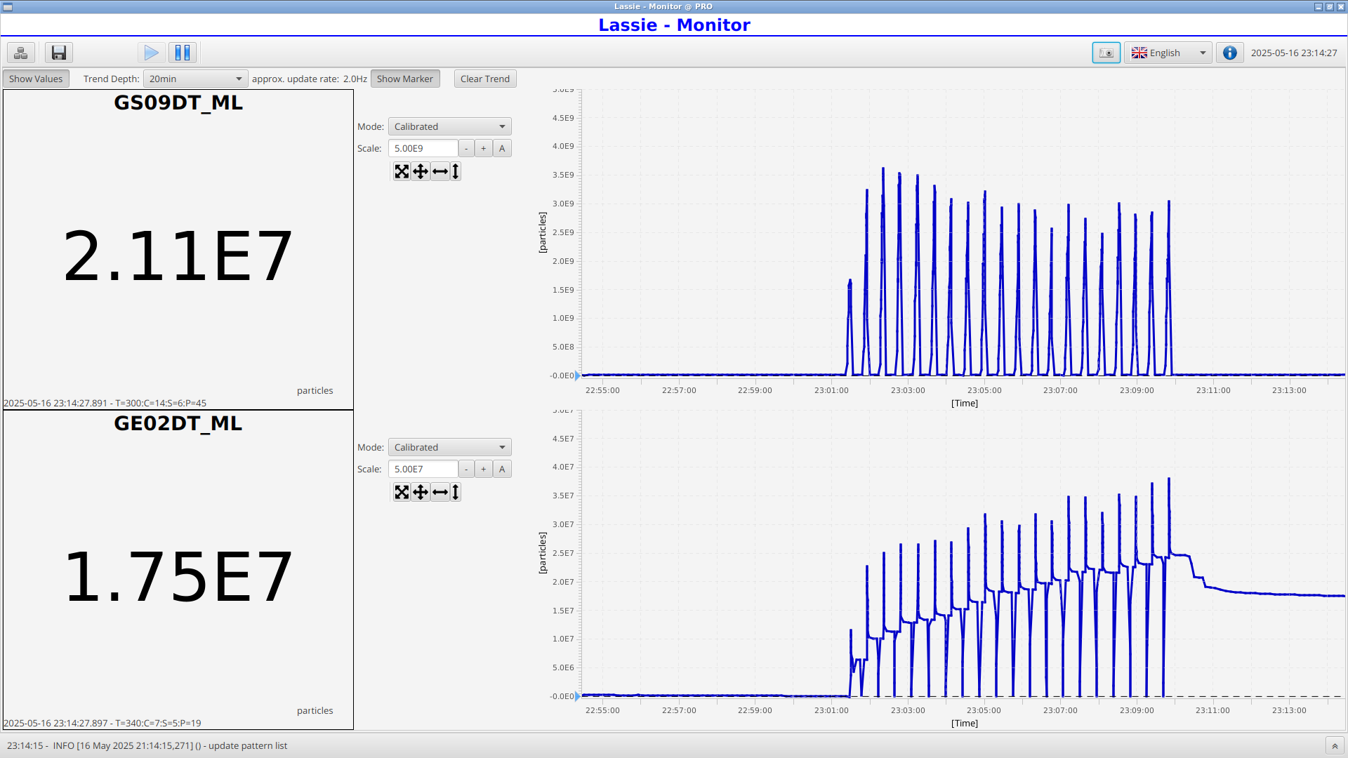
Dimitrios, Finn, Konstantin | Laser | Starting first laser scan |
NTCAP file name: SC_2025-05-16_22-54-39
We are starting now the laser scans. Therefore we changed the HV offset voltage back to 880V.
|
Time | File | PTB 32 | PTB 33 | Ohmlabs | ESR intensity SC8 / 1e6 | Typical SIS injections / 1e9 | comments | |
2025-05-16 23:00 | | | | | - | 2.5-3 | beam destroyed by scrapers | |
2025-05-16 23:35 | 101 | 205826 | 205827 | 205820 | 2 | 2.5-3.5 | Cooling gate cable was not plugged | |
2025-05-17 00:08 | 102 | 205826 | 205827 | 205820 | 2.5 | 2-3 | Particle detector did not drive in | |
2025-05-17 00:45 | 103 | 205826 | 205827 | 205820 | 2.1 | 3 | | |
2025-05-17 01:21 | 104 | 205826 | 205827 | 205820 | 2.1 | 2.5 | Changed Scanning range due to air wavelength error | |
2025-05-17 01:56 | 105 | 205826 | 205827 | 205820 | 2.5 | 3.3 | | |
2025-05-17 02:30 | 106 | 205826 | 205827 | 205820 | 1.9 | 3.7 | | |
2025-05-17 03:10 | 107 | 205826 | 205827 | 205820 | 1.1 | 3.7 | | |
2025-05-17 03:50 | 108 | 205826 | 205827 | 205820 | 2.4 | 3.4 | | |
2025-05-17 04:30 | 109 | 205826 | 205827 | 205820 | 1.9 | 3.2 | | |
2025-05-17 05:08 | 110 | 205826 | 205827 | 205820 | 1.9 | 3.3 | | |
2025-05-17 05:50 | 111 | 205826 | 205827 | 205820 | 2.3 | 3.3 | | |
2025-05-17 06:30 | 112 | 205826 | 205827 | 205820 | 2.6 | 3.4 | | |
|
Closed file |
| Attachment 1: 2025-05-16_23-14-28-051.png
|
|
|
82
|
Sat May 17 08:36:20 2025 |
Wilfried, Christopher, Kristian | Laser | Laser Scans in coasting beam |
switched to coasting beam
bucketfill (RF manipulation) (SC7, ...): [[3.0],[3.0]] ---> [[3.0],[0.0]]
|
Time | File | PTB 32 | PTB 33 | Ohmlabs | ESR intensity SC8 / 1e6 | Typical SIS injections / 1e9 | NTCAP file | comments | |
2025-05-17 07:43 | 113 | 205826 | 205827 | 205820 | 2 | 3.0 | SC_2025-05-17_08-18-54 | interestingly we see an ion beam after deceleration that is comparable to the bunched mode, even though yesterday evening the losses were a factor 3-4 higher in coasting beam mode | |
2025-05-17 08:34 | 114 | 205827 | 205828 | 205820 | 1.5 | 3.0 | SC_2025-05-17_09-00-28 | | |
2025-05-17 09:41 | 115 | 205821 | 205827 | 205829 | 0.9 | 2.5 | SC_2025-05-17_09-41-18 | late start of the laser scan. DR ramp stopped already at laser step 58. We see a resonance-like structure at laser step 28-32 | |
2025-05-17 10:20 | 116 | 205822 | 205827 | 205829 | 1.0 | 2.0 | SC_2025-05-17_10-19-49 | waited 30 s after initialization of ramp, then started laser scan | |
2025-05-17 10:58 | 117 | 205822 | 205828 | 205829 | 1.0 | 2.2 | SC_2025-05-17_10-57-38 | with waiting again | |
2025-05-17 11:37 | 117 | 205821 | 205826 | 205828 | 1.0 | 2.2 | SC_2025-05-17_11-15-37 | started NTCAP after injection #10, laser scan after waiting for 30s again, NTCAP not stopped, start of next injection cycle with about 10 injections included | |
|
|
|
83
|
Sat May 17 11:57:13 2025 |
Wilfried, Christopher, Kristian | Laser | Scans with bunched beam |
switched to bunched beam
bucketfill (RF manipulation) (SC7, ...): [[3.0],[0.0]] ---> [[3.0],[3.0]]
|
Time | File | Ohmlabs | PTB 32 | PTB 33 | ESR intensity SC8 / 1e6 | Typical SIS injections / 1e9 | NTCAP file | comments | |
2025-05-17 12:22 | 119 | 205820 | 205827 | 205829 | 1.0 | 2.2 | SC_2025-05-17_12-00-55 | laser spot is moving more than before | |
2025-05-17 13:00 | 120 | 205821 | 205826 | 205827 | 1.0 | 3 | SC_2025-05-17_13-00-45 | we asked HKR to optimize the SIS before the scan. The injected beam current is higher but not the final current in the ESR, started the ramp manually | |
2025-05-17 13:40 | 121 | 205821 | 205827 | 205828 | 1.0 | 3 | SC_2025-05-17_13-00-45 | | |
2025-05-17 14:30 | 122 | 205821 | 205827 | 205828 | 1.0 | 3 | | NTCAP ist angeblieben | |
|
|
|
84
|
Sat May 17 21:06:52 2025 |
Rodolfo, Christopher, Kristian | Laser | New dye |
We have exchanged the dye laser and filled the dye pumps with fresh dye. We also noticed that the seeder was off, we turned on again and set the pump energy to 350 mJ (at 532 nm).
The dye output energy is 150 mJ (at 592 nm) |
|
85
|
Sat May 17 21:27:17 2025 |
Wilfried, Rodolfo | Laser | Scraping the laser beam |
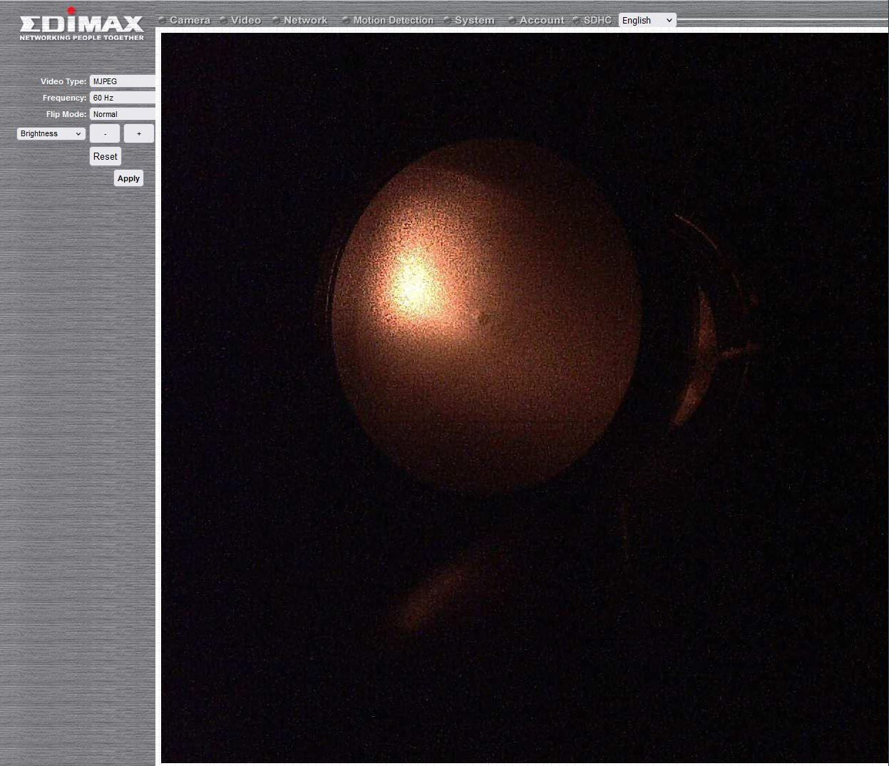
The beam stabilization in not working properly. So we have turned it off. We also scraped the laser beam at the E-Cooler and bring the laser beam to the right position.
The Scraper GECEDS2VU cannot move vertically. Moved scraper horizontally to the inner position. It does not disturb the injection. |
| Attachment 1: Laserspot_at_SO_2025-05-17.JPG
|
|
|
86
|
Sat May 17 21:40:40 2025 |
Wilfried, Rodolfo, Hendrik, Ragandeep, Yuri | Laser | Eveningshift data runs |
|
Time | File | Ohmlabs | PTB 32 | PTB 33 | ESR intensity SC8 / 1e6 | Typical SIS injections / 1e9 | NTCAP file | comments | |
2025-05-17 21:42 | 123 | 205820 | 20582X | 20582X | 6.5 | 3 | SC_2025-05-17_21-41-07 | mbs started, Go4 not connected, only written to disk, wrong scan region, we added 0.27 nm to values but should have subtracted it, see below ** | |
| 124 | | | | | | | file empty | |
2025-05-17 22:30 | 125 | 20582X | 20582X | 20582X | 6.5 | 2.7 | SC_2025-05-17_21-41-07 | mbs and laser scan started in SC8, before scraping, first and maybe second wavelength affected | |
2025-05-17 23:10 | 126 | 20582X | 20582X | 20582X | 0 | 2.7 | SC_2025-05-17_21-41-07 | beam killed by detectors | |
2025-05-17 23:42 | 127 | 20582X | 20582X | 20582X | 5 | 2.75 | SC_2025-05-17_21-41-07 |
|
** scan range was incorrect: For file #123 it was set to 593.42 nm - 592.82 nm
*** for #125, set to 592.85 nm - 592.25 nm |
|
87
|
Sun May 18 00:25:08 2025 |
Finn, Konstantin, Dimitrios | Laser | Nightshift data runs |
Took over from afternoon shift and keep scanning
|
Time | File | Ohmlabs | PTB 32 | PTB 33 | ESR intensity SC8 / 1e6 | Typical SIS injections / 1e9 | NTCAP file | comments | |
2025-05-17 23:50 | 128 | 205820 | 20582X | 20582X | 2.6 | 2.8 | SC_2025-05-17_21-41-07 | | |
2025-05-17 00:27 | --- | 205820 | 20582X | 20582X | --- | 2.5 | SC_2025-05-17_21-41-07 | Injection was stopped due to radiation alarm at HTD | |
2025-05-17 02:01 | 129 | 205820 | 20582X | 20582X | 3.0 | 2.2 | SC_2025-05-17_21-41-07 | beam back (intensity of SIS injection varies) | |
2025-05-17 02:36 | 130 | 205827 | 205828 | 205820 | 2.4 | 2.0 | SC_2025-05-17_21-41-07 | | |
2025-05-17 03:10 | 131 | --- | --- | --- | --- | --- | SC_2025-05-17_21-41-07 | empty file due to medusa crash | |
2025-05-17 03:10 | 132 | 205827 | 20582X | 20582X | 2.4 | 2.2 | SC_2025-05-17_21-41-07 | Started measurement to late, last step affected | |
2025-05-17 03:47 | 133 | 205827 | 20582X | 20582X | 3.0 | 2.3 | SC_2025-05-17_21-41-07 | | |
2025-05-17 04:24 | 134 | 205827 | 20582X | 20582X | 2.5 | 2.4 | SC_2025-05-17_21-41-07 | | |
2025-05-17 05:00 | 135 | 205827 | 20582X | 20582X | 3.9 | 2.4 | SC_2025-05-17_21-41-07 | | |
2025-05-17 05:35 | 136 | 205827 | 20582X | 20582X | 1.5 | 2.0 | SC_2025-05-17_21-41-07 | | |
2025-05-17 06:10 | 137 | 205827 | 20582X | 20582X | 3.6 | 2.4 | SC_2025-05-17_21-41-07 | | |
2025-05-17 06:46 | 138 | 205827 | 20582X | 20582X | 3.2 | 2.9 | SC_2025-05-17_21-41-07 | | |
2025-05-17 07:22 | 139 | 205827 | 20582X | 20582X | 3.6 | 1.8 | SC_2025-05-17_21-41-07 | Closed NTCAP file, Nightshift over and out | |
|
|
|
88
|
Sun May 18 01:47:56 2025 |
Konstantin | DAQ | Particle detector |
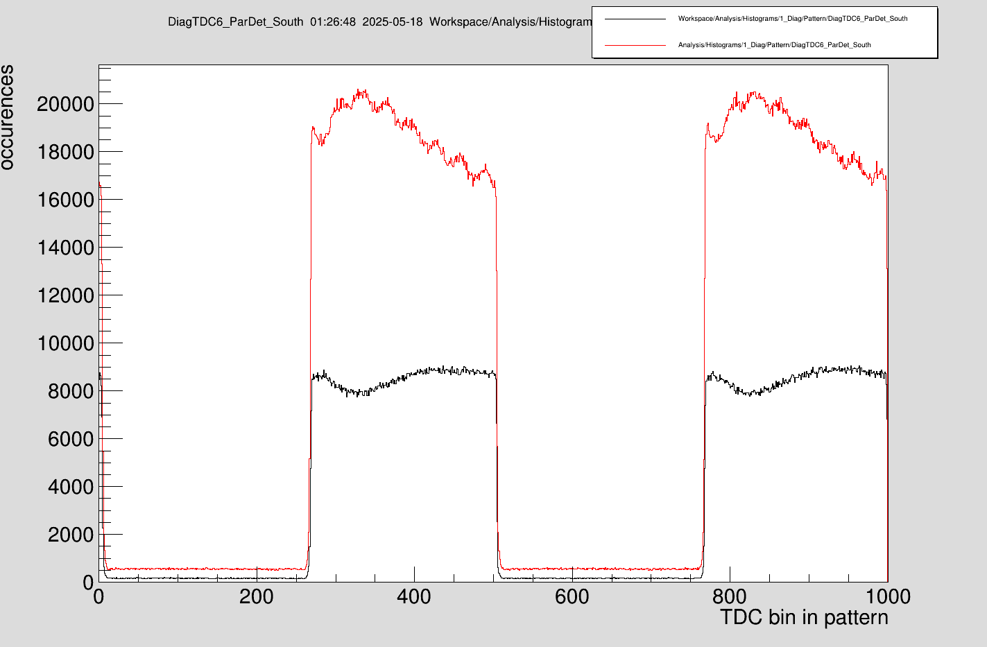
The attachment shows the signal of the particle detector for bunched beam (red, files 104-112) coasting beam (black, files 113-117) as a function of the time for one cycle of the DRALS pattern. One can identify modulations of the signal during the cooling step in both traces. However, there are some clear differences:
- Oscillation in bunched beam operation (maybe due to RF and cooler voltage offset?)
- While in coasting beam mode a steady state is reached, this is not observed in bunched beam operation.
|
| Attachment 1: ParticleDetectorModulation.png
|
|
|
89
|
Sun May 18 02:24:46 2025 |
Wilfried, Rodolfo, Carsten | Detectors | Antrieb Cu-Mirror defekt |
| On Saturday afternoon we moved the Cu mirror to the inner position, however an issue appeared when we tried to move the mirror to the "park" position. The stepping motor did not react properly, it clamped. After restarting the software we could actually move the mirror out, but the stepping motor as well as driving system made a lot of noise until the parking position was reached. This issue has to be investigated specialists after the beamtime. |
|
90
|
Sun May 18 04:33:46 2025 |
Dimitrios, Finn, Konstantin | Laser | Laser position |
| We changed the position of the laser back to the position which was set up in E 85 by changing the motor position of motor 4 in the kangoo software at ATPPC031 from -0.1 to -0.3. |
|
91
|
Sun May 18 08:06:55 2025 |
Danyal, Christopher, Jonas | Runs | morning shift |
Took over from night shift and keep scanning
|
Time | File | Ohmlabs | PTB 32 | PTB 33 | ESR intensity SC8 / 1e6 | Typical SIS injections / 1e9 | NTCAP file | comments | |
2025-05-18 08:21 | 140 | 205821 | 205827 | 205828 | 2.4 | 1.6 | SC_2025-05-18_07-57-22 | morning shift starts | |
2025-05-18 08:57 | 141 | 205821 | 205828 | 205829 | 3.3 | 1.4 | SC_2025-05-18_07-57-22 | | |
2025-05-18 09:32 | 142 | 205821 | 205828 | 205829 | 2.5 | 1.7 | SC_2025-05-18_07-57-22 | | |
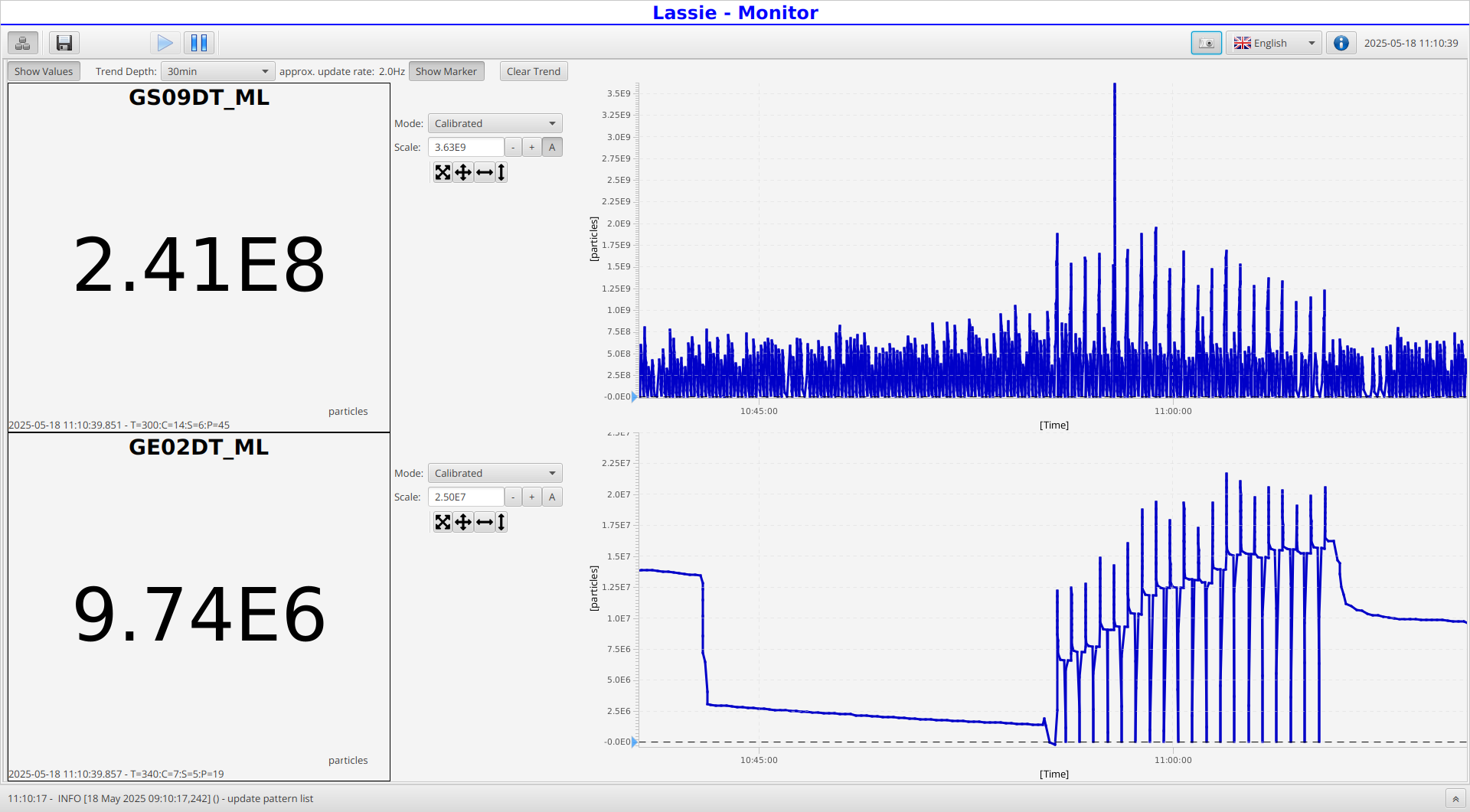
2025-05-18 10:08 | 143 | 205821 | 205828 | 205829 | 1.3 | 2.0 | SC_2025-05-18_07-57-22 | strong drop in ESR intensity after injection | |
2025-05-18 10:43 | 144 | 205822 | 205828 | 205829 | 3.4 | 1.8 | SC_2025-05-18_07-57-22 | | |
2025-05-18 11:19 | 145 | 205820 | 205828 | 205829 | 1.1 | 1.5 | SC_2025-05-18_07-57-22 | strong drop in ESR intensity after injection (see screenshot), laser scan started a few seconds too late | |
2025-05-18 11:55 | 146 | 205822 | 205828 | 205829 | 0.9 | 1.5 | SC_2025-05-18_07-57-22 | strong drop in ESR intensity after injection, worse than before, decreasing SIS intensity | |
2025-05-18 12:00 | | | | | | | | called HKR, reported ESR drop, they checked but see no clear reason, ESR crew will be called for help, see 2nd screenshot | |
2025-05-18 12:15 | | | | | | | | Sergey called, we should stop requesting after ESR cycle, then send "ganzen Kontext" (ParamModi) and then request beam again | |
2025-05-18 12:29 | 147 | 205822 | 205828 | 205829 | 0.4 | 1.0 | SC_2025-05-18_07-57-22 | again drop in ESR intensity after injection, SIS18 intensity was increased during accumulation | |
2025-05-18 12:40 | | | | | | | | we sent "ganzen Kontext" (ParamModi) and then request beam again | |
2025-05-18 13:04 | 148 | 205821 | 205828 | 205829 | 1.3 | 2.5 | SC_2025-05-18_07-57-22 | looks better now | |
2025-05-18 13:15 | | | | | | | | stopped ESR cycle, stopped NTCAP, Sergey will check ESR settings, maybe improvement is possible | |
2025-05-18 13:45 | | | | | | | | ESR cycle running but was interrupted, DRALS was still running, we waited until DRALS end, then started ESR cycle again. We changed time between SIS18 injections from 40 s to 20 s | |
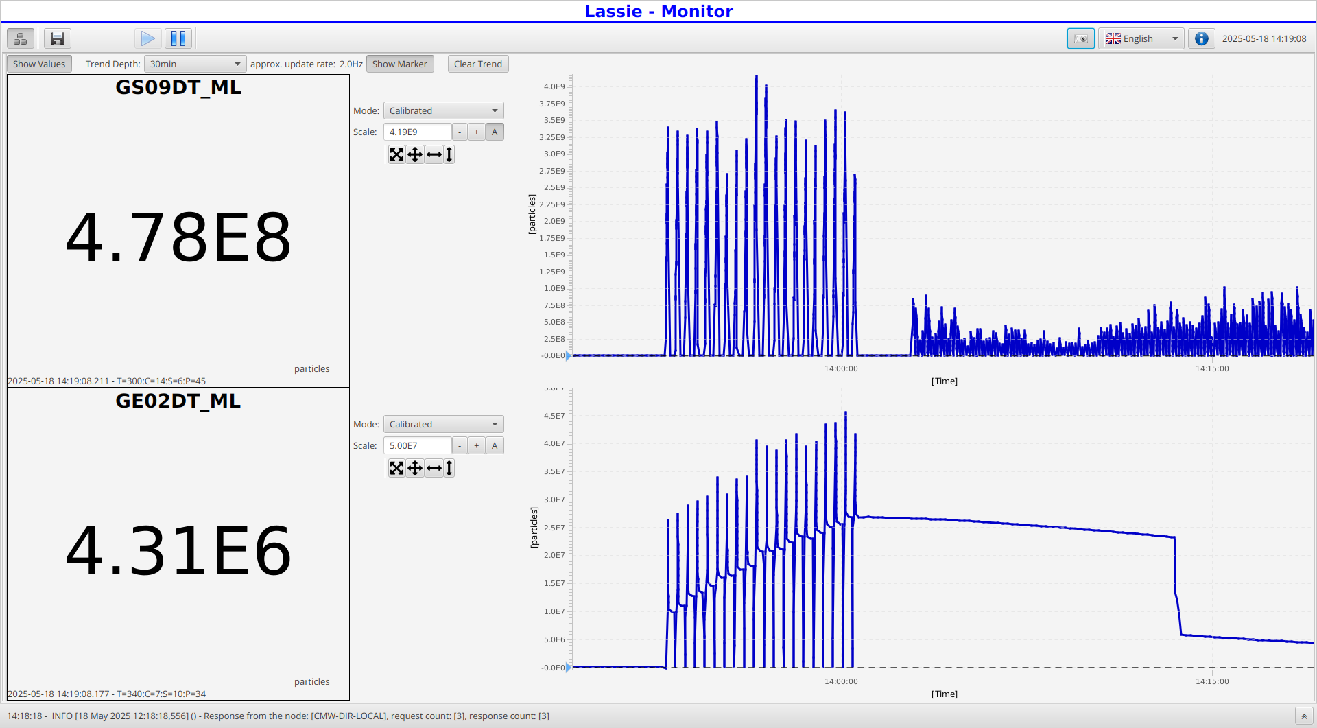
2025-05-18 14:14 | 149 | 205826 | 205833 | 205834 | 5.7 | 3.5 | SC_2025-05-18_13-52-38 | the losses after injection (in SC5) are gone!! (see 3rd screenshot) HV values slightly drifted, ~5 V | |
2025-05-18 14:49 | 150 | 205819 | 205826 | 205827 | 2.6 | 2.5 | SC_2025-05-18_13-52-38 | slight SC5 losses again, and HV values again slightly drifted, ~3 V | |
2025-05-18 15:24 | 151 | 205821 | 205828 | 205829 | 1.8 | 2.3 | SC_2025-05-18_13-52-38 | slight SC5 losses again, HV values back to normal | |
2025-05-18 16:00 | 152 | 205824 | 205831 | 205832 | 0.7 | 2.6 | SC_2025-05-18_13-52-38 | low ESR intensity, HV slightly different | |
|
|
| Attachment 1: 2025-05-18_11-10-39-917_tcl1146.png
|
|
| Attachment 2: Bildschirmfoto_2025-05-18_12-22-37.png
|

|
| Attachment 3: 2025-05-18_14-19-08-249_tcl1146.png
|
|
|
92
|
Sun May 18 16:08:58 2025 |
Wilfried, Carsten, Rodolfo, Hendrik | Runs | Afternoon shift, continued measurements |
Took over from morning shift and keep scanning
|
Time | File | Ohmlabs | PTB 32 | PTB 33 | ESR intensity SC8 / 1e6 | Typical SIS injections / 1e9 | NTCAP file | comments | |
2025-05-18 16:35 | 153 | 205821 | 205827 | 205817 | 0.8 | 2.3 | SC_2025-05-18_13-52-38 | Inconsistent SIS Injections, Voltages all drifted slightly, checked the beam positions by moving the scraper on the remaining ions after scan, Scraper GECEDS2HU was used and the horizontal alignment was confirmed to still be good, Carsten re-sent some SIS commands but changed nothing | |
2025-05-18 17:38 | 154 | 205822 | 205828 | 205829 | 0.7 | 2.0 | SC_2025-05-18_13-52-38 | Unlucky SIS injections, Voltages do not drift much anymore, beam after scan was used to scrape again, checked vertical alignment with GECEDS1VU, ion beam located at -0.5, laser beam still clearly visible, around 4mm too high compared to ion beam, GECEDS1HU confirms horizontal alignment is also good like in Scraper 2 | |
2025-05-18 18:43 | 155 | 205824 | 205830 | 205831 | 0.9 | 2.5 | SC_2025-05-18_13-52-38 | GECEDS1HU destroyed ion beam at -13.0 | |
2025-05-18 19:32 | 156 | 205822 | 205829 | 205830 | 0.8 | 3.0 | SC_2025-05-18_13-52-38 | First few SIS injections were very bad, after that very good, 0.5 on GECEDS2VU and the ion beam vanishes, fits good with laser beam, delay of the laser reduced by 7ns | |
2025-05-18 20:21 | 157 | 205822 | 205828 | 205830 | 0.8 | 2.4 | SC_2025-05-18_13-52-38 | | |
2025-05-18 20:57 | 158 | 205822 | 205828 | 205830 | 0.7 | 2.5 | SC_2025-05-18_13-52-38 | | |
2025-05-18 21:38 | 159 | 205820 | 205826 | 205828 | 1.3 | 2.8 | SC_2025-05-18_13-52-38 | | |
2025-05-18 22:13 | 160 | 205820 | 205826 | 205827 | 1.0 | 2.8 | SC_2025-05-18_13-52-38 | | |
2025-05-18 22:46 | 161 | 205820 | 205826 | 205827 | 1.7 | 2.9 | SC_2025-05-18_13-52-38 | | |
2025-05-18 23:22 | 162 | 205822 | 205829 | 205830 | 3.5 | 2.7 | SC_2025-05-18_13-52-38 | While scanning, at step 16 something weird happened and the accumulated counts decreased only in that step | |
2025-05-18 00:00 | 163 | 205822 | 205828 | 205829 | 5.0 | 2.8 | SC_2025-05-18_13-52-38 | 22 injections and 75 breeding cycles | |
|
Timing: We shifted the laser approximately 8 ns to an earlier time to compensate for the 2-3 m distance between the target and the detection region (please note that earlier times are located to the right since the x-axis is the time after the event until the common stop). The positions of the laser pulse on the photodiodes are therefore shifted to the right. |
| Attachment 1: Bildschirmfoto_2025-05-18_21-10-46.png
|
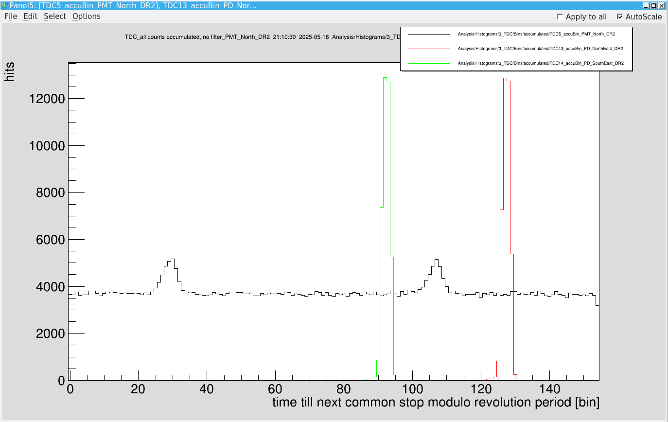
|
|
93
|
Sun May 18 21:30:20 2025 |
Wilfried, Rodolfo, Markus, Zoran | Accelerator | T-Scrapers, Update |
Here are the right instructions to drive the T-Scrapers inside the ESR Electron Cooler
- ECEDS1VU: Verriegelt mit ECEDS1HA. Der Antrieb kann nur fahren
wenn der Antrieb ECEDS1HA in Position -4,0 steht.
- ECEDS1HA: Verriegelt mit ECEDS1VU. Der Antrieb kann nur fahren
wenn der Antrieb ECEDS1VU in Stellung EI steht.
- ECEDS2VU: Verriegelt mit ECEDS2HA. Der Antrieb kann nur fahren
wenn der Antrieb ECEDS2HA in Position 0,0 steht.
- ECEDS2HA: Verriegelt mit ECEDS2VU. Der Antrieb kann nur fahren
wenn der Antrieb ECEDS2VU in Stellung EI steht.
According to Boywitt/Schuhmacher, BEA-MEI. Date: 28.07.2021 |
|
94
|
Mon May 19 00:28:40 2025 |
Simon, Finn | Runs | Night shift measurement |
Took over from afternoon shift and keep scanning
|
Time | File | Ohmlabs | PTB 32 | PTB 33 | ESR intensity SC8 / 1e6 | Typical SIS injections / 1e9 | NTCAP file | comments | |
2025-05-19 00:20 | 164 | 205822 | 205828 | 205829 | 3.8 | 1.5 | SC_2025-05-18_13-52-38 | week injections from SIS | |
2025-05-19 00:50 | 165 | 205822 | 205828 | 205829 | 5.0 | 2.6 | SC_2025-05-18_13-52-38 | | |
2025-05-19 01:23 | 166 | 205822 | 205828 | 205829 | 5.3 | 5.3 | SC_2025-05-18_13-52-38 | file empty: medusa crashed | |
2025-05-19 01:23 | 167 | ? | ? | ? | --- | --- | SC_2025-05-18_13-52-38 | problem with normalization in Go4: cleaned histograms | |
2025-05-19 02:00 | 168 | ? | ? | ? | 0.5 | 2.6 | SC_2025-05-18_13-52-38 | bad injections/stacking | |
2025-05-19 02:37 | 171 | ? | ? | ? | 4.5 | 2.8 | SC_2025-05-18_13-52-38 | mbs crashed due to overfull buffer, restarted mbs | |
2025-05-19 03:36 | 173 | ? | ? | ? | 5.5 | 2.9 | SC_2025-05-18_13-52-38 | | |
2025-05-19 04:14 | 174 | ? | ? | ? | 5.4 | 2.9 | SC_2025-05-18_13-52-38 | | |
2025-05-19 04:50 | 175 | ? | ? | ? | 5.3 | 2.8 | SC_2025-05-18_13-52-38 | | |
2025-05-19 05:26 | 176 | ? | ? | ? | 5.4 | 2.9 | SC_2025-05-18_13-52-38 | | |
2025-05-19 06:02 | 177 | ? | ? | ? | 0.9 | 3.1 | SC_2025-05-18_13-52-38 | great losses after stacking and after breeding | |
2025-05-19 06:39 | 178 | ? | ? | ? | 5.1 | 2.9 | SC_2025-05-18_13-52-38 | we changed the scan range to 592.7 - 592.1nm | |
2025-05-19 07:15 | 179 | ? | ? | ? | 4.9 | 2.9 | SC_2025-05-18_13-52-38 | | |
2025-05-19 07:51 | 180 | ? | ? | ? | 4.9 | 2.9 | SC_2025-05-18_13-52-38 | medusa crashed again | |
2025-05-19 08:27 | 181 | ? | ? | ? | 4.9 | 2.8 | SC_2025-05-18_13-52-38 | | |
|
After file 168 we noticed that the connection between mbs and medusa looked faulty, so we restarted mbs and restored the connection. But we could not get the voltage divider readout back running.
Files 166,168-172 are empty/incomplete.
After file 177 we saw a peak at the predicted wavelength in the histogram with subtracted background. To confirm this, we changed the scan range to 592.7 - 592.1nm, which should move the peak to the left of the histogram. |
| Attachment 1: Bildschirmfoto_2025-05-19_05-56-15.png
|
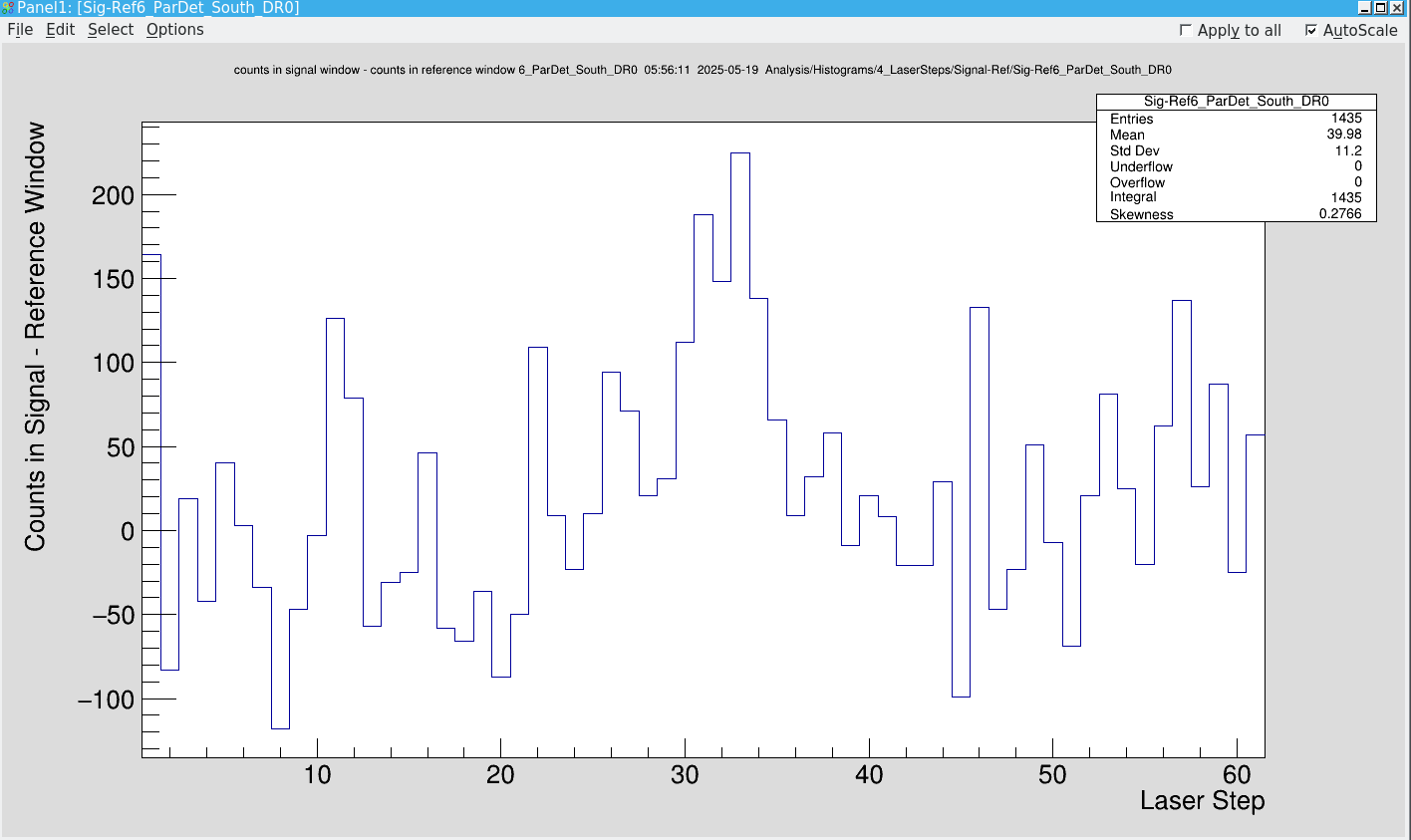
|
| Attachment 2: Bildschirmfoto_2025-05-19_05-56-41.png
|
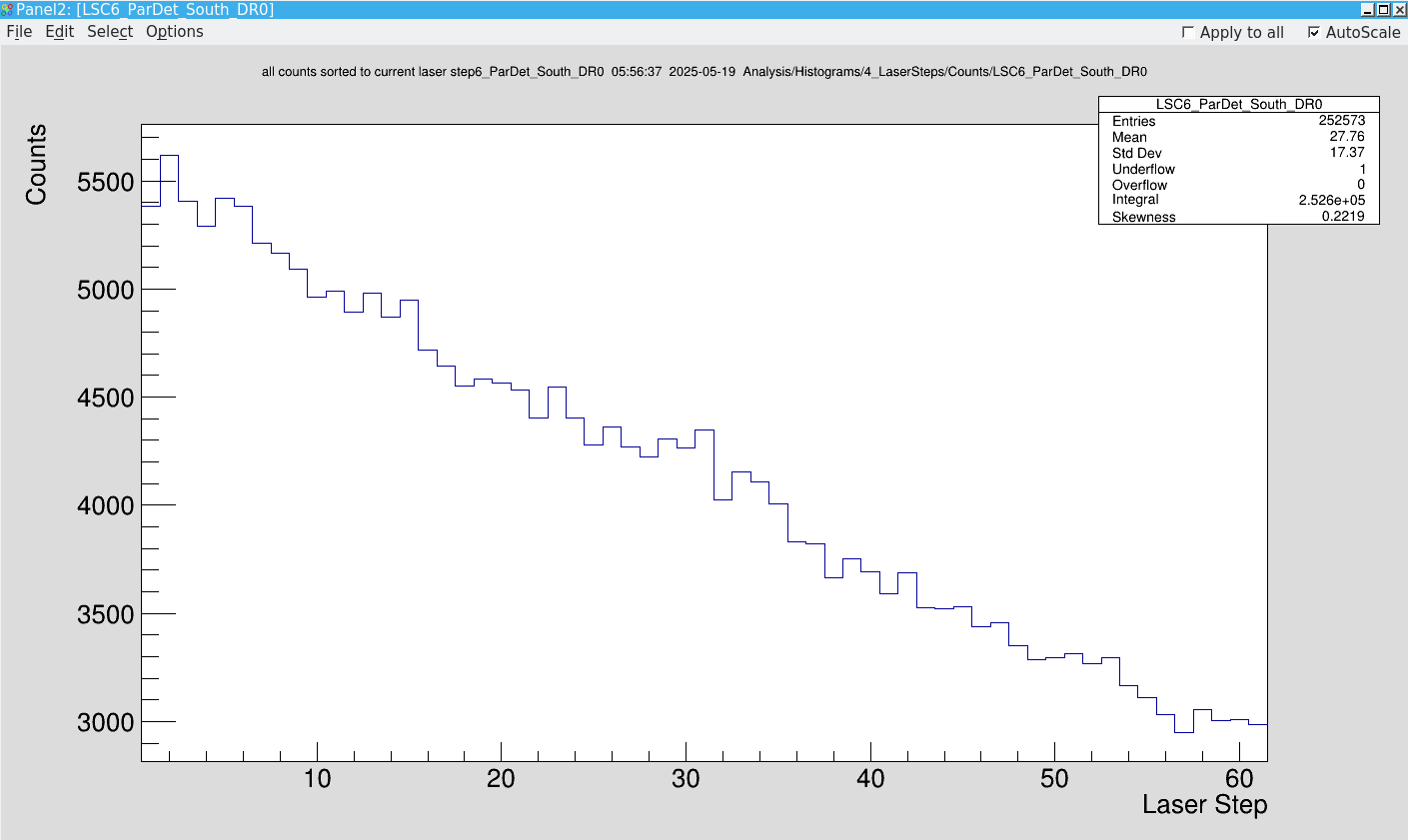
|
|
95
|
Tue May 27 10:56:44 2025 |
Konstantin | DAQ | Common stop |
The common stop was wired through a 1:2, and subsequently through a 1:99 rate divider channel. However, since the pulse width was too long, the 1:2 channel was translated into a 1:4 reduction. This must be considered, when the data is processed via go4. The reduction factor in the SetParameters.C file must be set to 198 accordingly. |